
Skip to main contentSkip to footer

Isolated RS485 Modbus RTU Slave Module: IS4310-ISO485M1

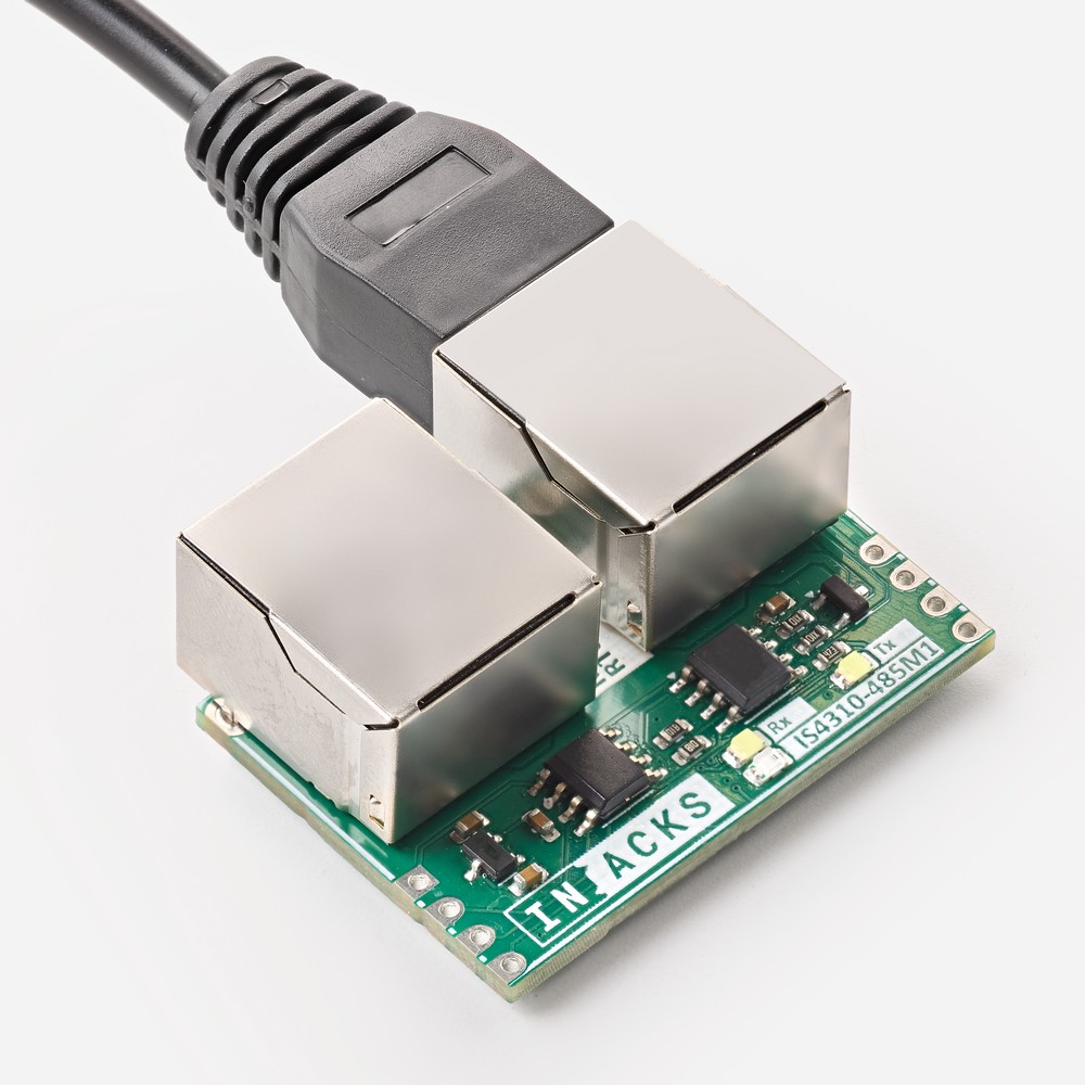
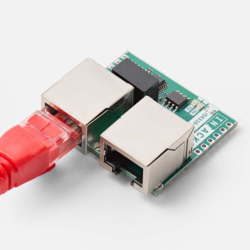
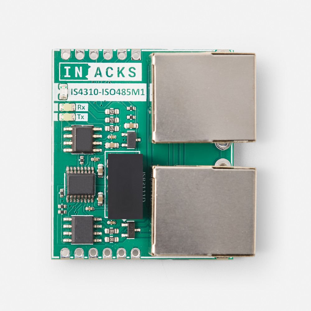
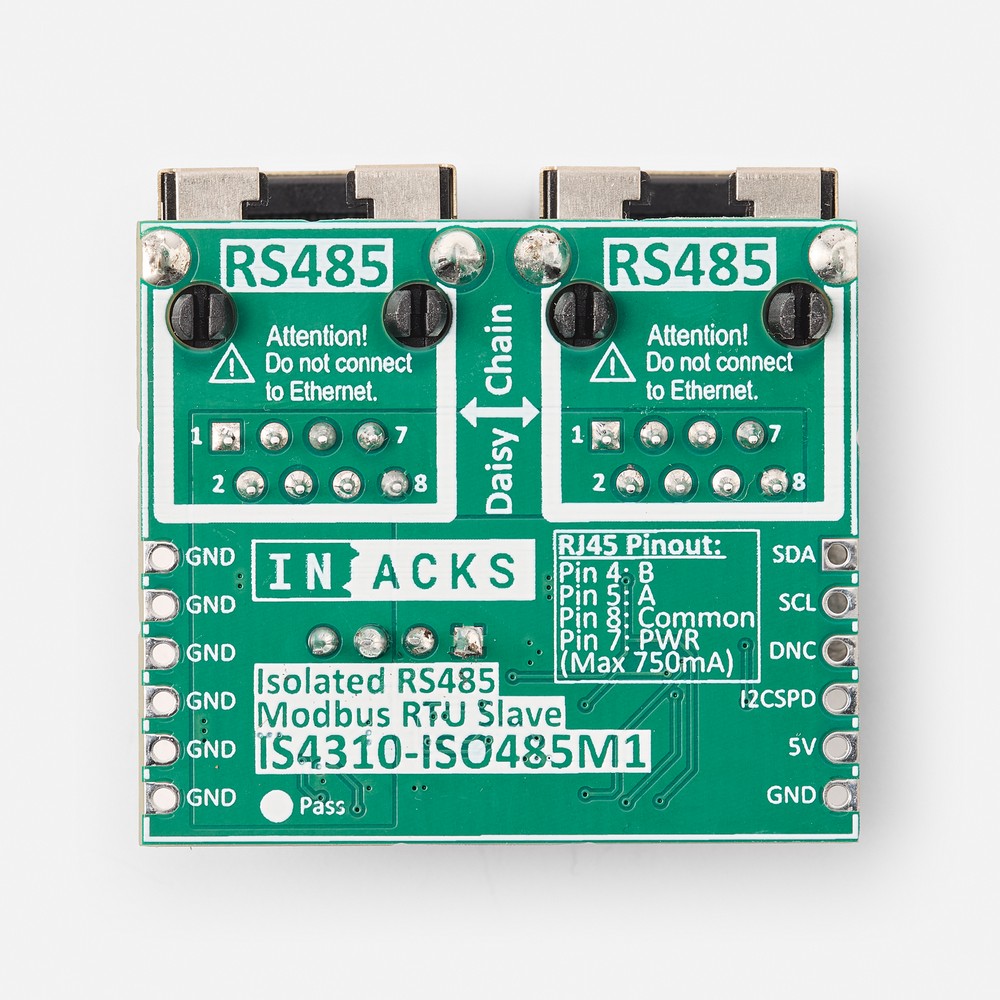
Isolated RS485 Modbus RTU Slave with two daisy-chained RJ45 connectors

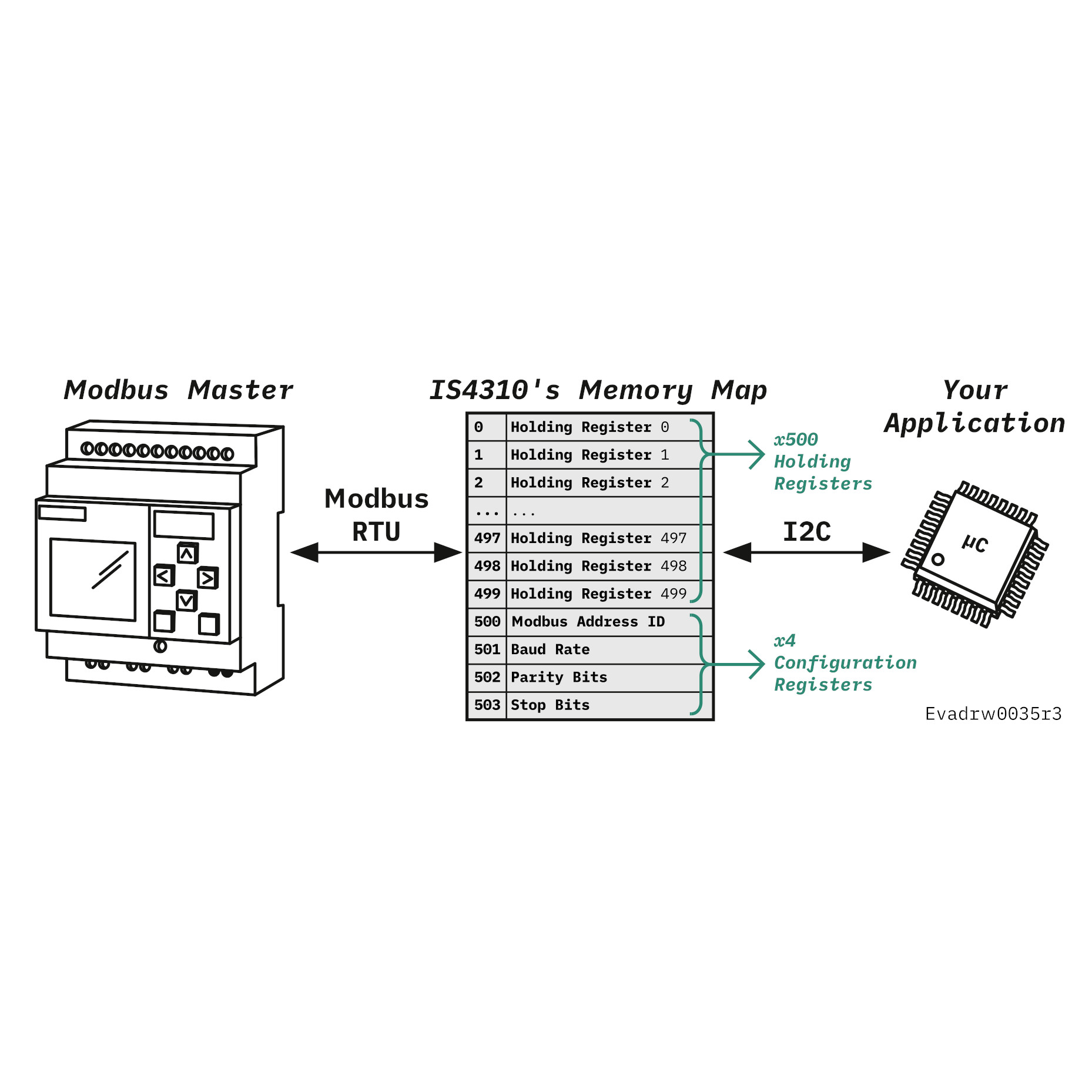
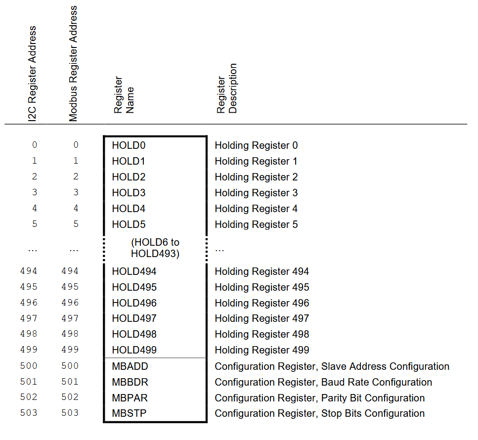
500 Holding Registers for user data, accessible via I2C

Available Function Codes:
– 0x03 Read Holding Registers
– 0x06 Write Single Register
– 0x10 Write Multiple Registers

Default Modbus Settings:
– Modbus Slave ID: 1
– Modbus Baud Rate: 19200 bps
– Modbus Parity: Even
– Modbus Stop Bits: 1

I2C Characteristics:
– I2C Slave Address: 0x11 (fixed)
– I2C Speed: 100 kHz, 400 kHz, 1 MHz
– I2C Voltage: 3.3 V (5 V tolerant)

Out of stock

SKU: IS4310-ISO485M1

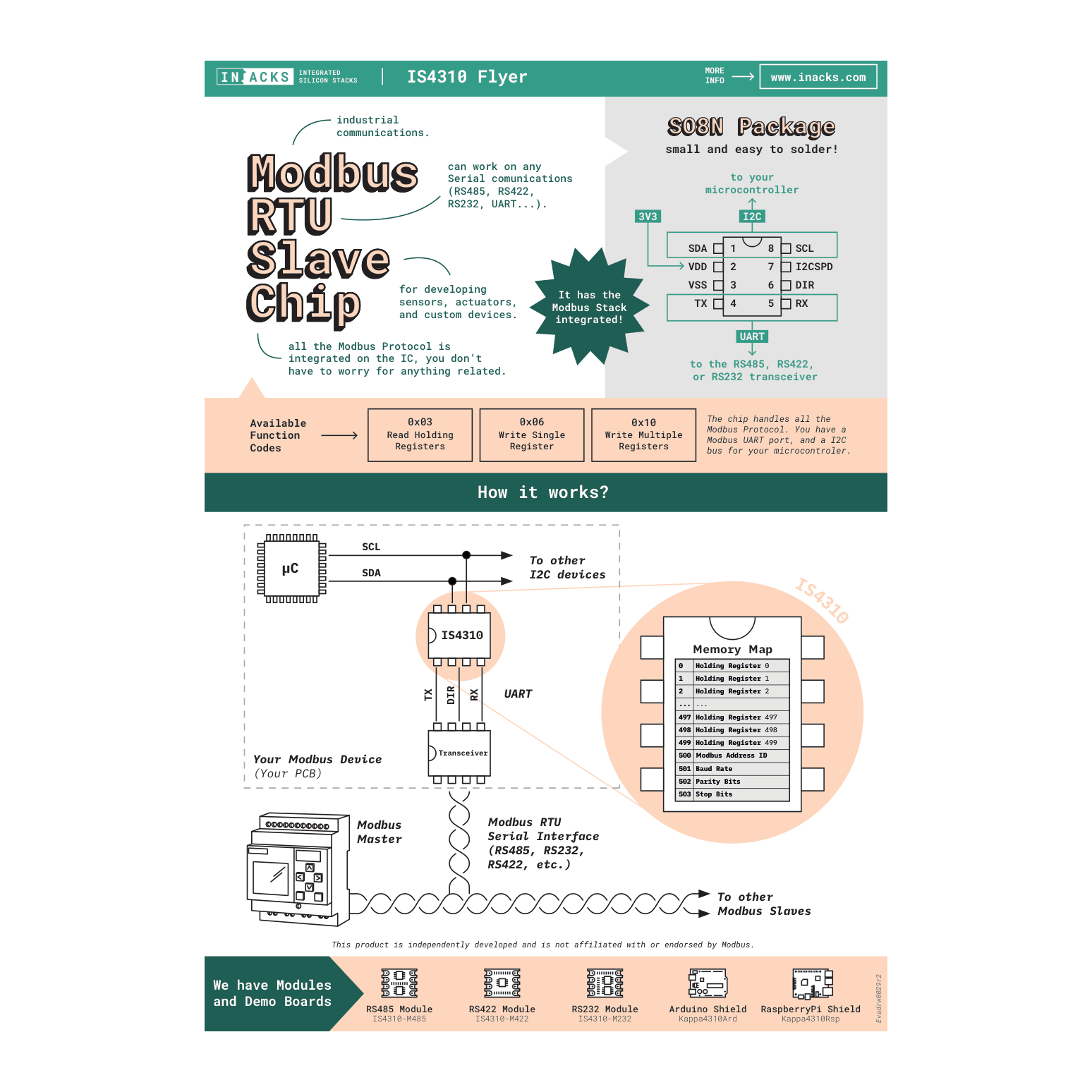
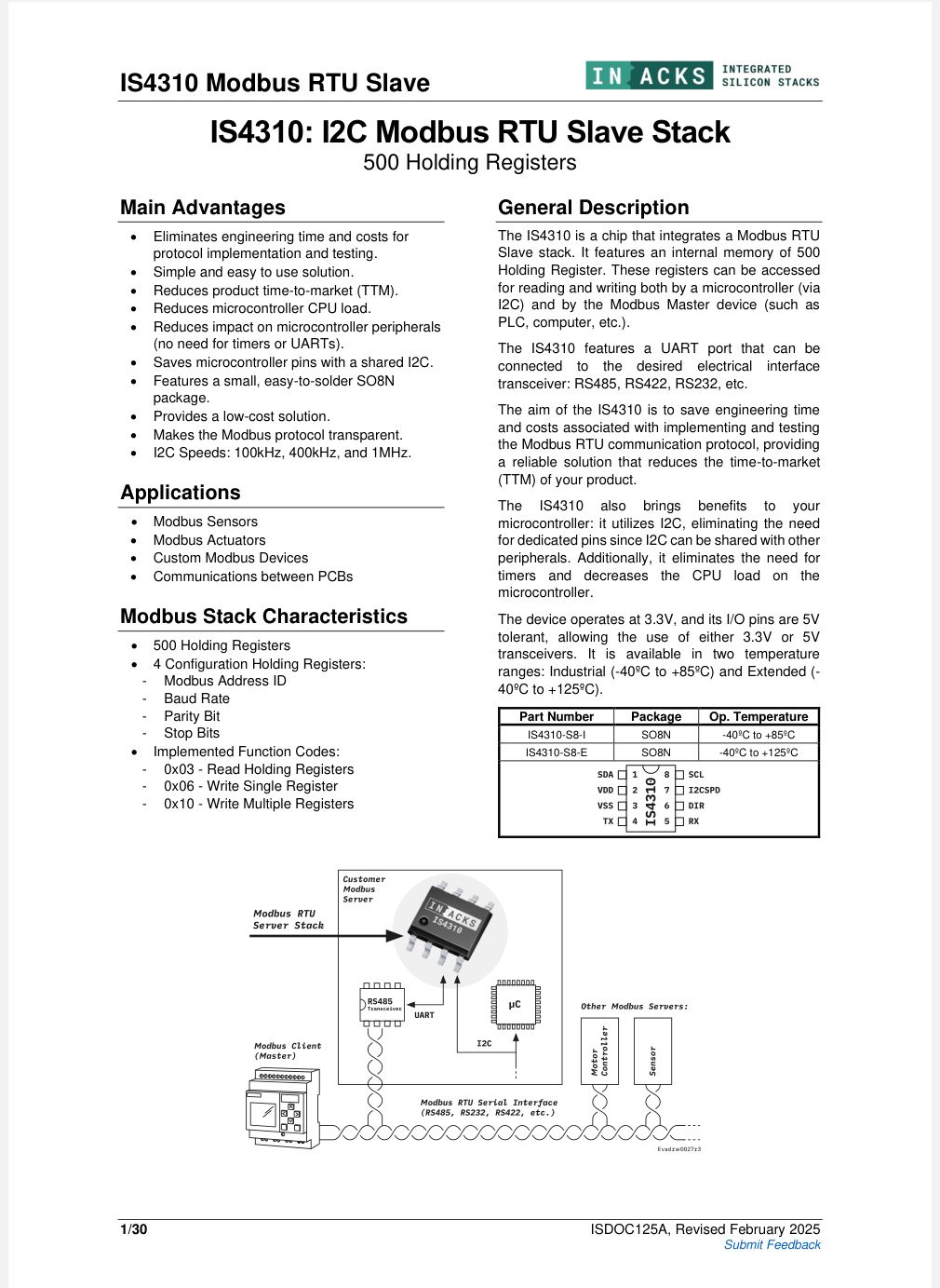
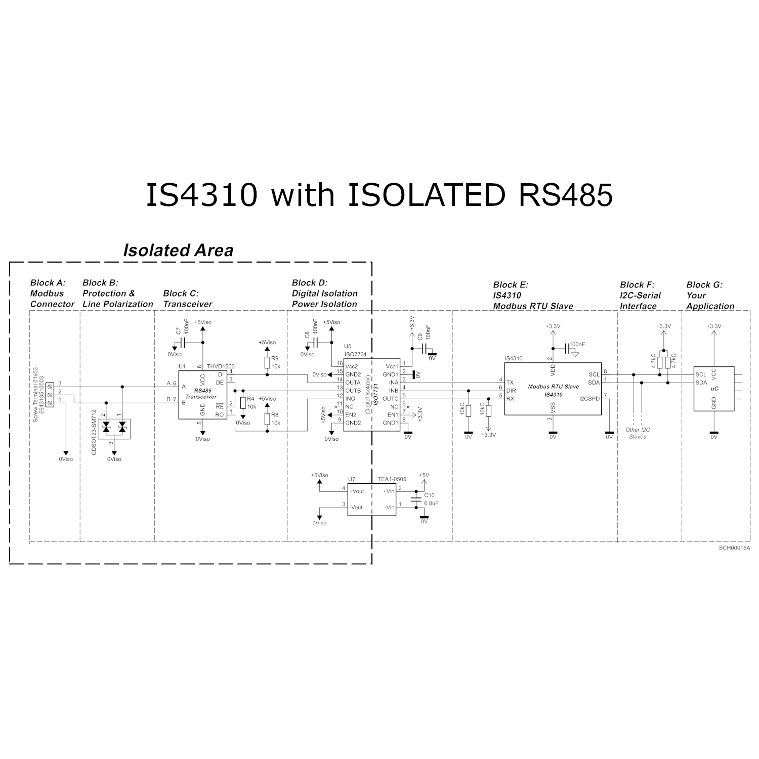
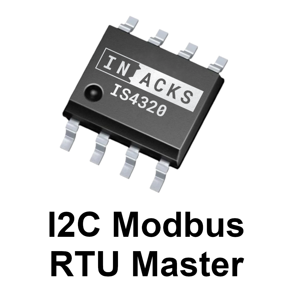
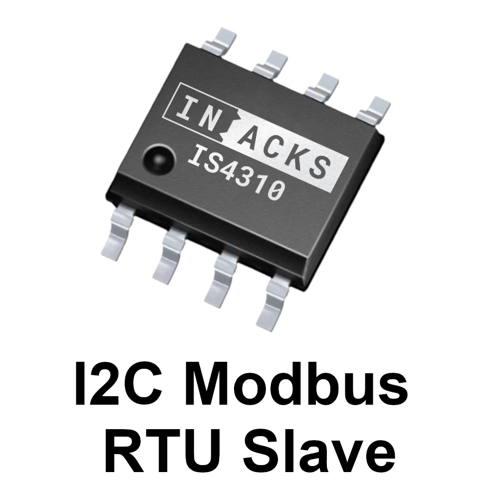
The IS4310-ISO485M1 is an isolated RS485 Modbus RTU slave module that adds a Modbus RTU interface to any microcontroller, FPGA, Arduino or Raspberry Pi through I2C. It combines the IS4310 Modbus RTU slave chip, an isolated RS485 transceiver and two daisy-chained RJ45 connectors. The galvanic isolation makes it a robust choice for harsh electrical environments and long cable runs with ground potential differences.

How the Isolated RS485 Modbus RTU Slave Module Works

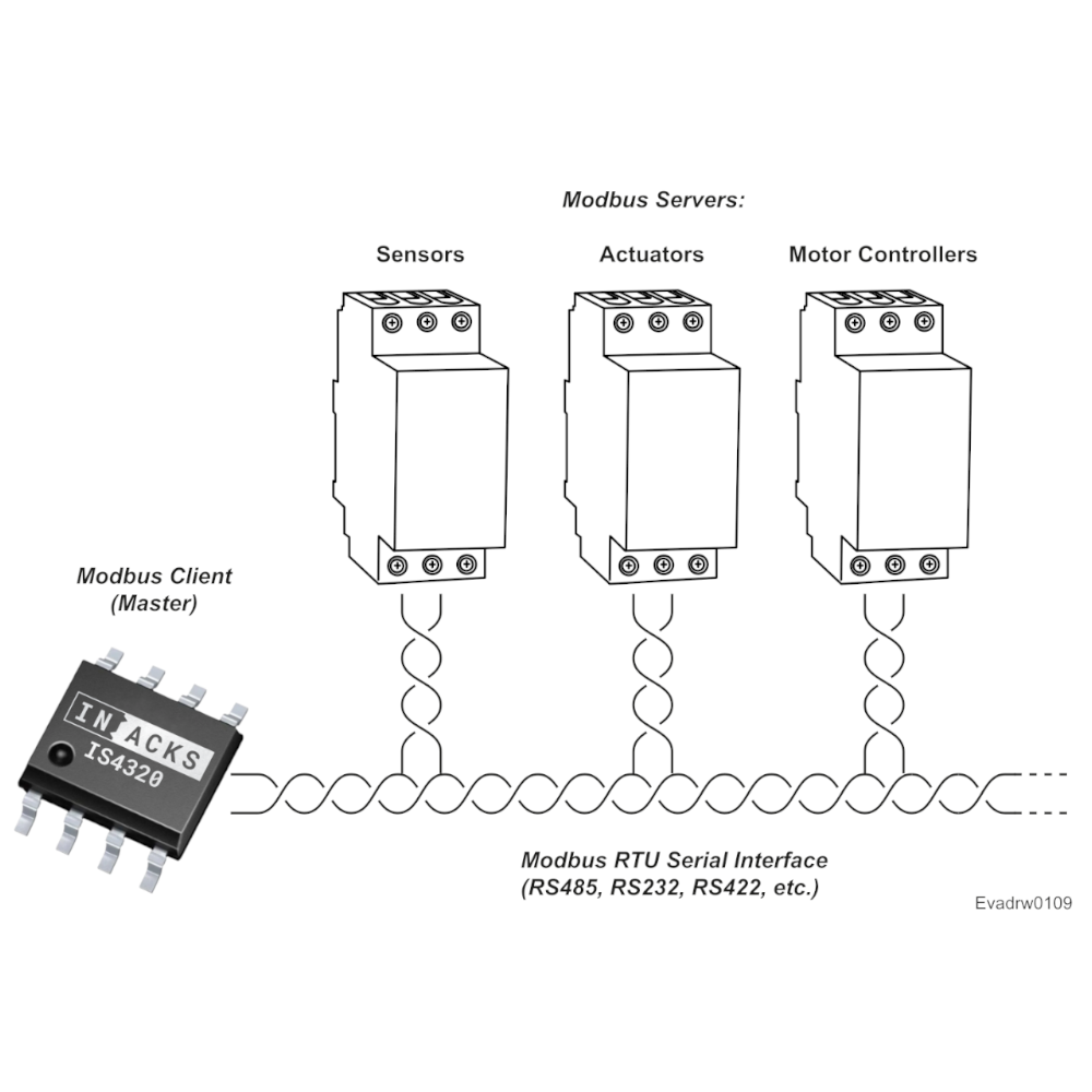
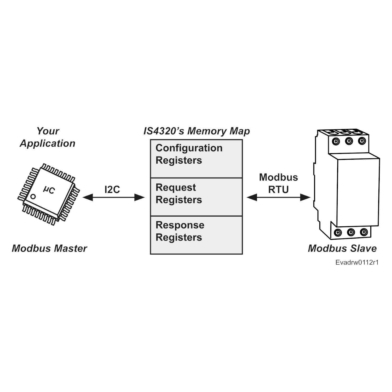
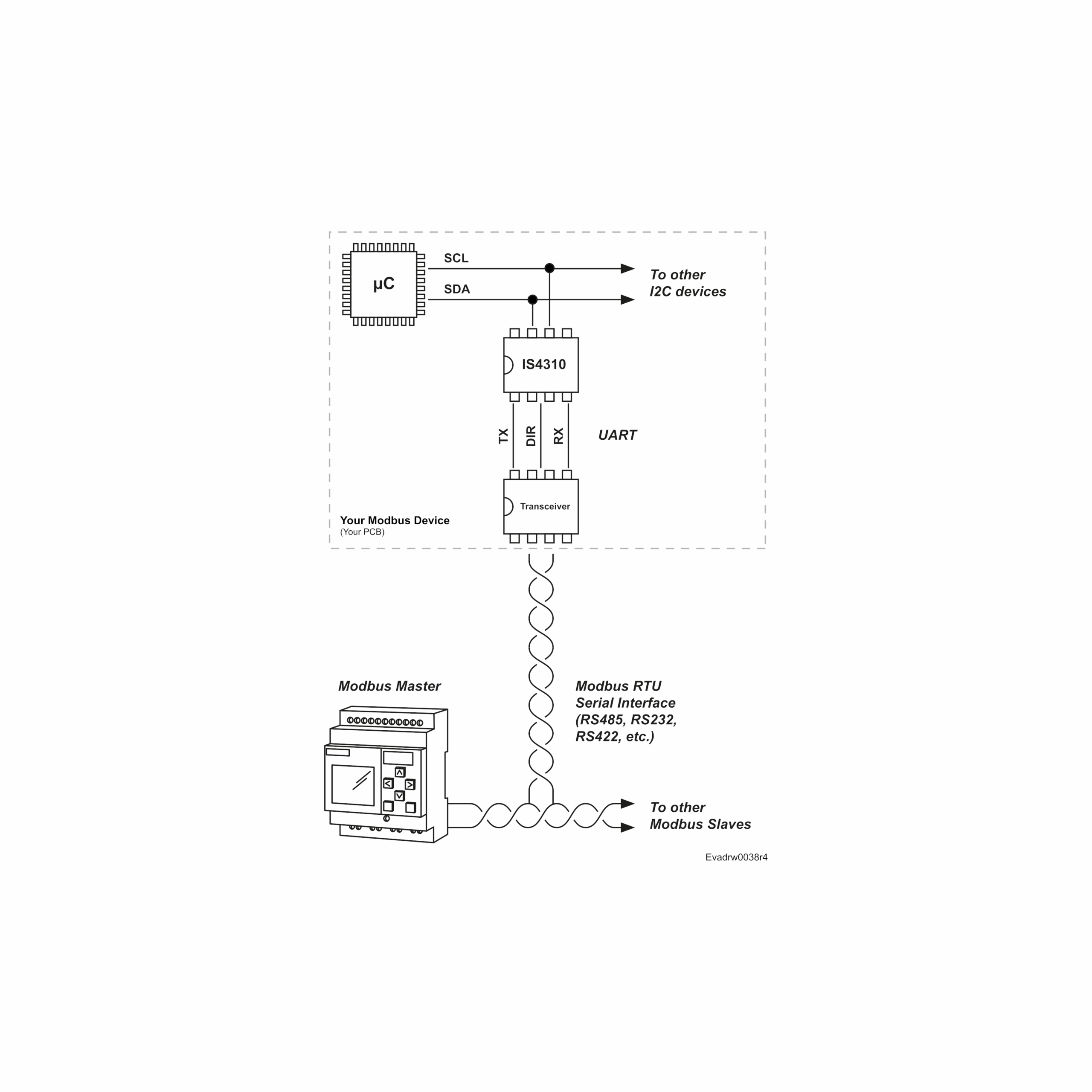
The IS4310 runs the complete Modbus RTU protocol, so no Modbus stack or library is required. Your system only reads and writes the 500 Holding Registers over I2C: whatever it writes can be read by the Modbus master (PLC, computer or machine), and whatever the master writes can be read by your system. The I2C speed (100 kHz, 400 kHz or 1 MHz) is selected with the I2CSPD pin.

Use it as a:

  • Sensor: your system writes measurements and the master reads them.
  • Actuator: the master writes commands and your system reads them to drive relays, motors or LEDs.
  • Mixed: both at the same time.

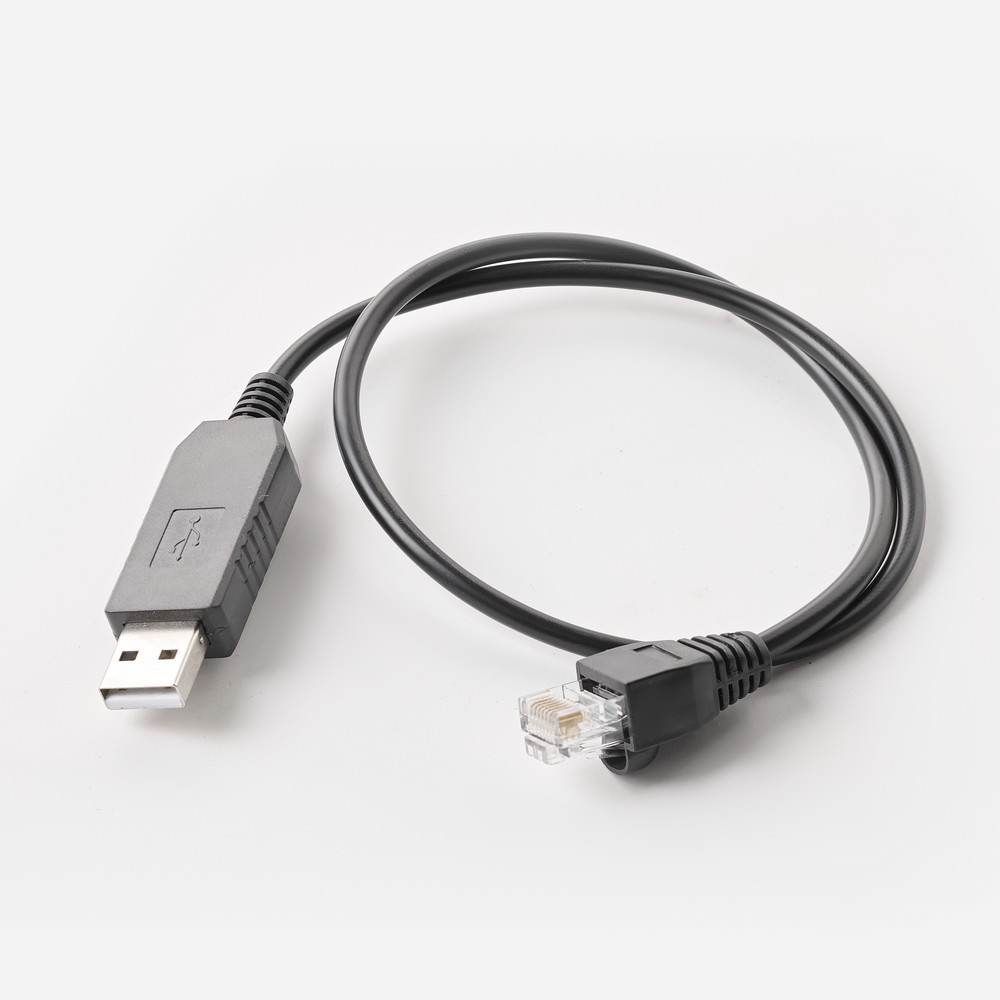
The Examples tab shows how to build a Modbus RTU relay board with a Raspberry Pi in a few lines of Python. To test the module from your PC, use our USB Dongle for Modbus RTU with free software such as qModMaster.

Integrate the IS4310 in Your Own Design

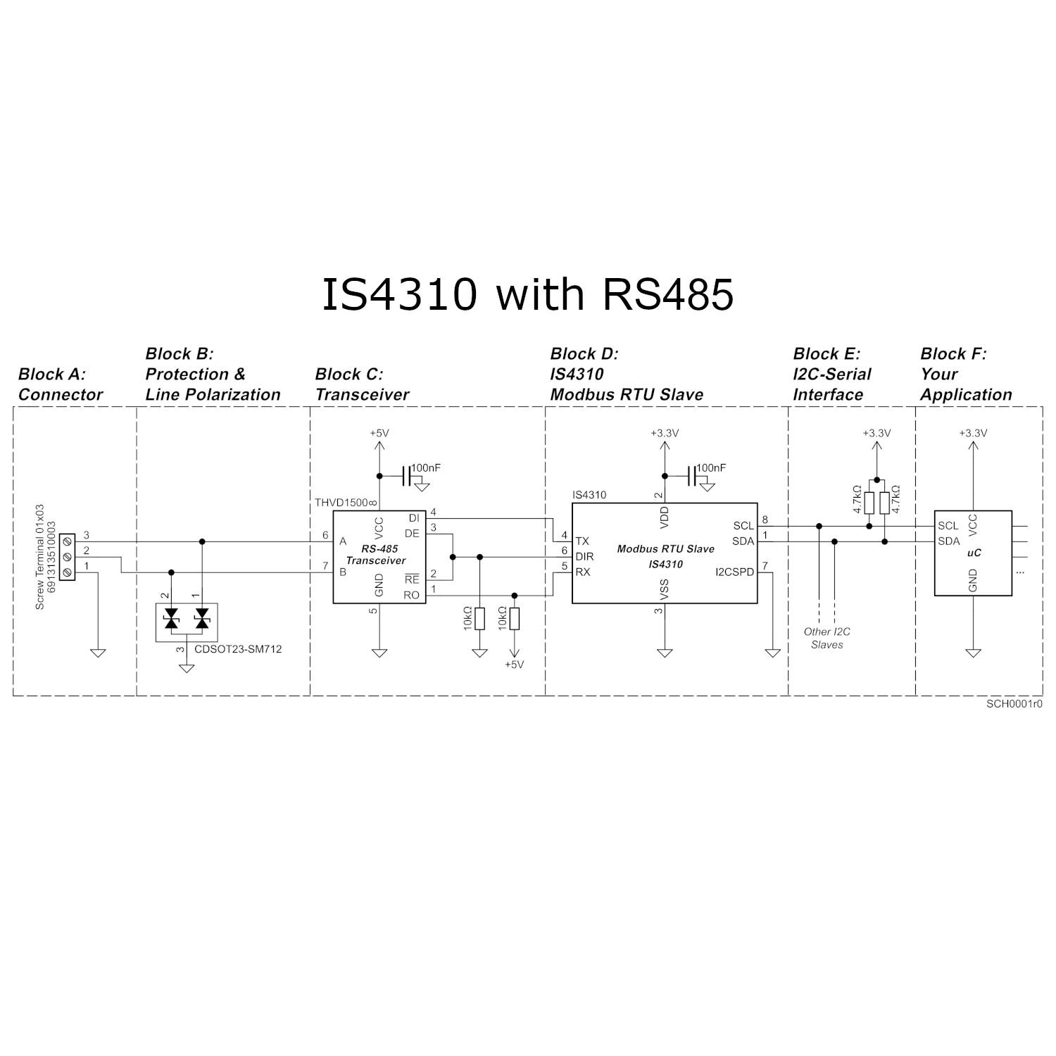
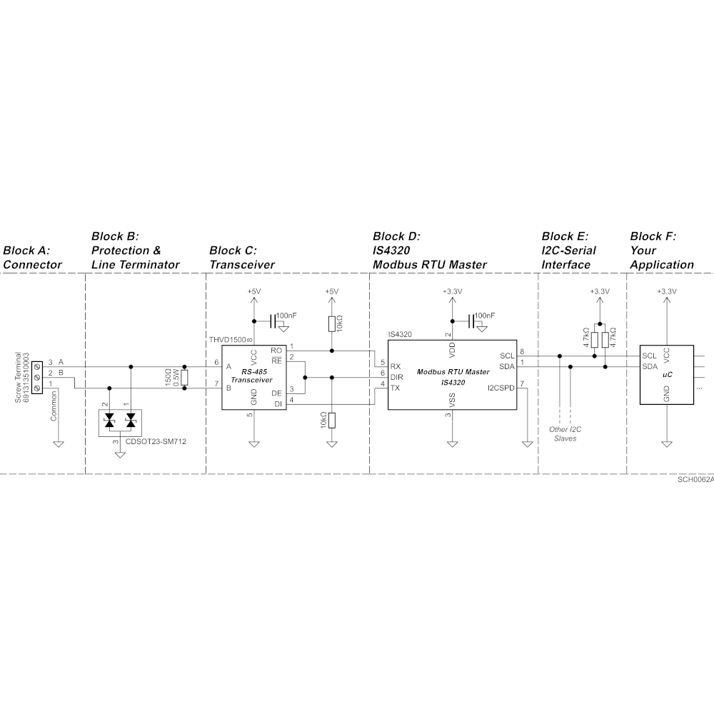
To minimize costs and customize the connector, you can also integrate the IS4310 chip directly in your own design. Example schematics are in the IS4310 datasheet. Don’t need isolation? Check the non-isolated IS4310-485M3 RS485 module.
Module Documentation

IS4310-ISO485M1 User Manual
IS4310-ISO485M1 Schematic

IS4310 Documentation

IS4310 Datasheet
IS4310 Online Wiki
IS4310 Brochure

Modbus Test Tools

USB Dongle for Modbus RTU (connects your PC to the RS485 bus)
qModMaster (free Modbus RTU Master software for Windows)

Q: What does the IS4310-ISO485M1 do?

A: It adds an isolated RS485 Modbus RTU slave interface to any device with I2C. Your microcontroller, FPGA, Arduino or Raspberry Pi reads and writes 500 Holding Registers over I2C, and the module answers the Modbus master on the RS485 bus.

Q: Do I need a Modbus library or protocol stack?

A: No. The IS4310 chip on the module runs the complete Modbus RTU slave stack. Your code only reads and writes registers over I2C.

Q: Which Modbus function codes are supported?

A: 0x03 Read Holding Registers, 0x06 Write Single Register and 0x10 Write Multiple Registers.

Q: What are the default settings?

A: Modbus Slave ID 1, 19200 bps, Even parity and 1 Stop Bit. The I2C slave address is 0x11 (fixed).

Q: Why choose the isolated version?

A: The RS485 bus is galvanically isolated from your electronics, which protects your design against ground potential differences and noise on long cable runs and in harsh electrical environments. If you don’t need isolation, the IS4310-485M3 is the non-isolated alternative.

Q: Does it work with Raspberry Pi and Arduino?

A: Yes. The I2C pins work at 3.3 V and are 5 V tolerant. The Examples tab shows a Raspberry Pi Modbus relay board and links to Arduino and STM32 code.

Q: How do I power the module?

A: Supply 5 V to the +5V pad. The module regulates the 3.3 V for the IS4310 on board.

Q: Can I connect the RJ45 to an Ethernet network?

A: No. The RJ45 connectors carry RS485 signals with the standard Modbus pinout. Never connect them to an Ethernet switch, router or PC network port.

Q: How can I test it from my PC?

A: Use our USB Dongle for Modbus RTU with free Modbus master software such as qModMaster.

Raspberry Pi Example: Modbus RTU Relay Board

This example turns a Raspberry Pi and the IS4310-ISO485M1 into a 4-channel Modbus RTU relay board. The Modbus master (PLC, SCADA or PC) writes Holding Registers 0 to 3, and the Raspberry Pi reads them over I2C and switches the relays: 0 = relay OFF, any other value = relay ON.

1. Wiring

IS4310-ISO485M1 Raspberry Pi
+5V Pin 2 (5V)
GND Pin 6 (GND)
SDA Pin 3 (GPIO2 / SDA)
SCL Pin 5 (GPIO3 / SCL)
I2CSPD GND (100 kHz, the Raspberry Pi default I2C speed)

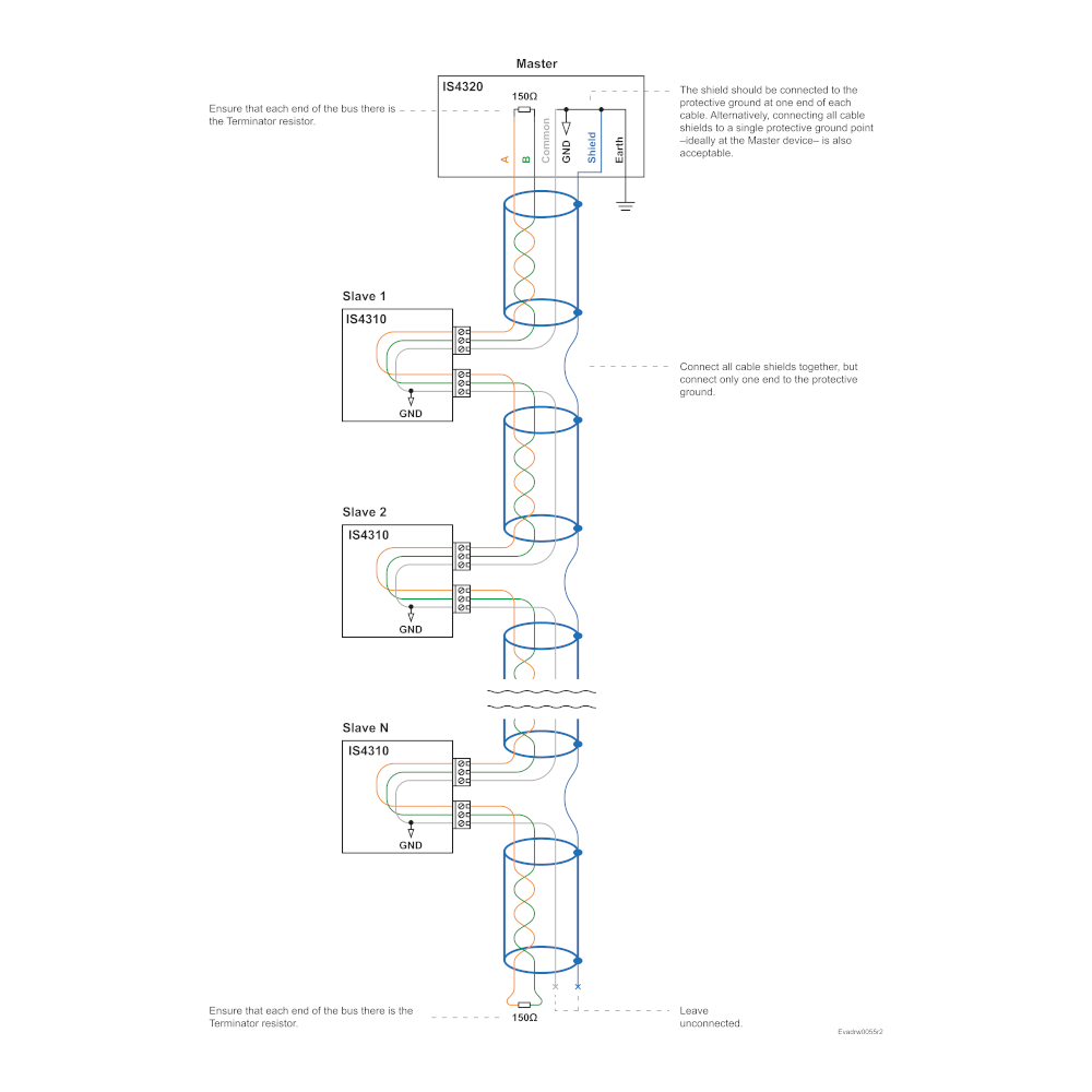
Connect the relay board inputs IN1, IN2, IN3 and IN4 to GPIO17, GPIO27, GPIO22 and GPIO23 (pins 11, 13, 15 and 16), and power the relay board from the Raspberry Pi 5V and GND pins. The Raspberry Pi already has pull-up resistors on SDA and SCL. Finally, connect the RJ45 connector to your Modbus RS485 bus.

2. Prepare the Raspberry Pi

Enable I2C with sudo raspi-config → Interface Options → I2C. Then install the libraries and check that the module answers at address 0x11 (you should see 11 in the table):

sudo apt install -y python3-smbus2 python3-gpiozero i2c-tools
i2cdetect -y 1

3. The Code: relay_board.py

#!/usr/bin/env python3
"""
Modbus RTU relay board with a Raspberry Pi and the IS4310-ISO485M1.

A Modbus master writes Holding Registers 0 to 3 over RS485.
The Raspberry Pi reads them from the IS4310 over I2C and switches 4 relays:
0 = relay OFF, any other value = relay ON.
"""
import time
from smbus2 import SMBus, i2c_msg
from gpiozero import OutputDevice

IS4310_I2C_ADDRESS = 0x11          # Fixed I2C address of the IS4310
RELAY_GPIOS = [17, 27, 22, 23]     # Relays 1-4, controlled by Holding Registers 0-3
RELAY_ACTIVE_HIGH = True           # Set to False if your relay board is active-low

relays = [OutputDevice(gpio, active_high=RELAY_ACTIVE_HIGH) for gpio in RELAY_GPIOS]


def read_holding_register(bus, register):
    """Read one 16-bit Holding Register (address and value are sent MSB first)."""
    set_address = i2c_msg.write(IS4310_I2C_ADDRESS, [register >> 8, register & 0xFF])
    read_value = i2c_msg.read(IS4310_I2C_ADDRESS, 2)
    bus.i2c_rdwr(set_address, read_value)
    high, low = list(read_value)
    return (high << 8) | low


try:
    with SMBus(1) as bus:          # I2C bus 1: GPIO2 (SDA), GPIO3 (SCL)
        while True:
            for register, relay in enumerate(relays):
                relay.value = read_holding_register(bus, register) != 0
            time.sleep(0.1)
except KeyboardInterrupt:
    pass

4. Run and Test

python3 relay_board.py

With the default Modbus settings (Slave ID 1, 19200 bps, Even parity, 1 Stop Bit), use function code 0x06 Write Single Register to write 1 to Holding Register 0: relay 1 switches ON. Write 0 to switch it OFF. Holding Registers 1, 2 and 3 control relays 2, 3 and 4. You can test it from your PC with the USB Dongle for Modbus RTU and qModMaster.

Tip: many relay boards are active-low (the relay turns on when its input is LOW). If your relays work inverted, set RELAY_ACTIVE_HIGH = False.

More Firmware Examples

Evaluation boards, Modules & other related products

Evaluation boards, modules, and accessories designed for fast prototyping and easy integration. Featuring standard interfaces and built-in transceivers, they simplify testing and development across platforms like Arduino, Nucleo, or Raspberry Pi. Ideal for adding RS485, RS232, or Ethernet functionality with minimal effort and maximum compatibility.

Have a question?

Fill out this field
Please enter a valid email address.
Fill out this field
You need to agree with the terms to proceed