
Modbus TCP Server Module for Your Microcontroller
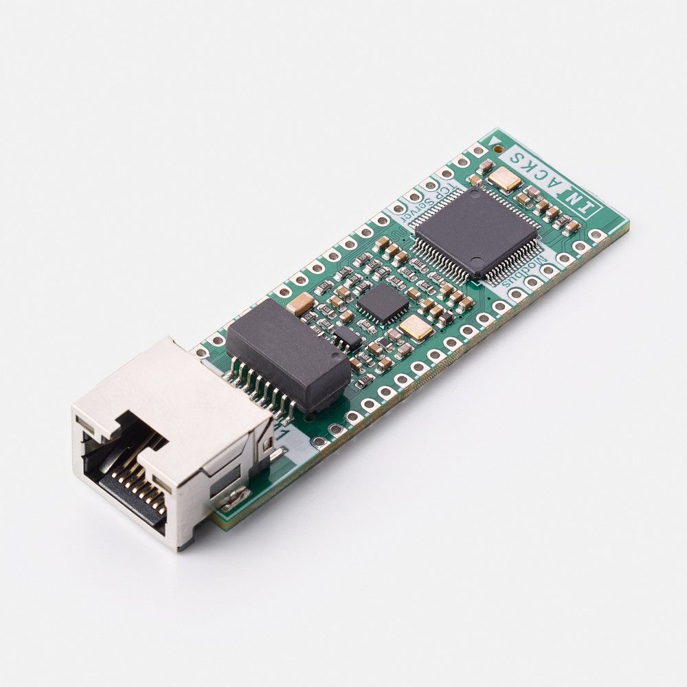
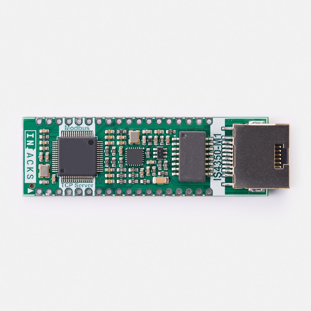
The IS4350-M1 is a ready-to-use Modbus TCP server module that turns any microcontroller with an I2C port into a Modbus TCP/IP server. The board integrates the IS4350 I2C Modbus TCP/IP Server IC, the LAN8742A 10/100 Ethernet PHY and the Ethernet magnetics. It also includes ESD protection and an RJ45 connector with status LEDs, all pre-designed and tested.
Designing an Ethernet interface from scratch requires a PHY, its reference clock and its strap configuration. It also requires impedance-controlled RMII and MDI routing, magnetics, line termination and a shielded RJ45 connector. The IS4350-M1 contains all of this. Your design only has to provide 3.3 V, two I2C lines and a few configuration pins. The module then takes care of the Ethernet link, the TCP/IP stack and the Modbus protocol.
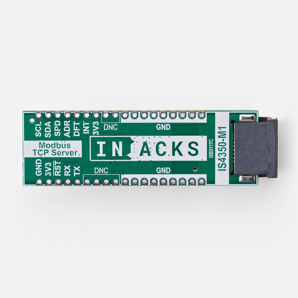
As a result, this Modbus TCP server module saves you from developing any TCP/IP or Modbus stack. You do not need to design any Ethernet hardware either. In addition, the module has 36 castellated pads on a 2.54 mm pitch. You can solder it directly onto your PCB as a surface-mount component, or fit pin headers for prototyping and evaluation.
Applications
- Sensors and transmitters: make temperature, pressure, flow or level readings available to a PLC or SCADA system.
- Actuator and motor controllers: receive set-points and commands from a PLC over Ethernet.
- Remote I/O modules: map digital and analog inputs and outputs to Holding Registers.
- Energy meters and power monitors: publish voltage, current, power and energy values.
- Building automation and HVAC controllers: connect your controllers to the building management system.
- Data acquisition and test equipment: share your measurements with any PC or HMI on the network.
How the Modbus TCP Server Module Works
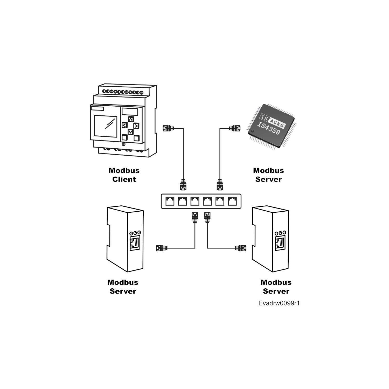
The IS4350 implements the complete Modbus TCP/IP server. It exposes 65,500 Holding Registers that your microcontroller and any Modbus client can read and write. The Modbus client can be a PLC, a SCADA system, an HMI or a PC. The Holding Registers work as a shared memory. Your firmware writes measurements for the client to read, and it reads the set-points and commands that the client writes.
From your microcontroller’s point of view, the IS4350-M1 behaves like an I2C memory with 16-bit addresses and 16-bit registers. Therefore, you do not need any Ethernet driver, TCP/IP stack or Modbus library: standard I2C reads and writes are enough. For example, a temperature sensor writes its reading to Holding Register 0 (HOLD_0) and keeps it updated.
- I2C (host interface): your microcontroller, as the I2C master, reads and writes the Holding Registers and the configuration registers.
- Ethernet (RJ45): Modbus clients connect to port 502 and access the same Holding Registers with function codes 03, 06 and 16.
- INT pin (optional): sends a pulse of about 100 ms whenever a Modbus client writes a register. Your firmware can then react without polling.
Starting the Modbus Server
At power-up, the Modbus server stays offline until your firmware starts it. First, write valid data to your Holding Registers. Then, write 1 to the GO_ONLINE register (address 65513) and wait until the STATUS register (address 65514) reports 5: the server is ready and listening on port 502.
By default, the module uses DHCP and a MAC address generated from the IS4350 serial number. Consequently, no network configuration is needed. You can also set a static IP address, subnet mask and gateway over I2C or Modbus.
Safety Features
The Modbus TCP server module also includes several safety mechanisms for industrial products:
- I2C CRC protection (I2C-CRC): tie the CRC pin to 3.3 V, and a CRC-16/Modbus checksum protects every I2C read and write. The module discards any write with a wrong CRC.
- I2C watchdog timer (I2C-WDT): start the server by writing 2 instead of 1 to GO_ONLINE. If your microcontroller stops refreshing it for 500 ms, the module stops the Modbus server. Clients never read stale data.
- Fail-safe power-up: the server never comes online by itself. It cannot publish data while your microcontroller is starting up or has failed.
- Network recovery: if a wrong setting makes the module unreachable, hold the DEF pin high for 3 seconds. The module restores the default network configuration.
- Firmware updates: keep the IS4350 up to date with security patches and new releases through the provisioning UART (TX and RX pins).
Key Features
- Modbus TCP/IP server: 65,500 Holding Registers, function codes 03, 06 and 16, port 502, one client connection.
- Ethernet: 10/100 Mbps, with on-board LAN8742A PHY, KMS-1102NL magnetics and USBLC6-4SC6 ESD protection.
- RJ45 connector with link/activity (yellow) and speed (green) LEDs.
- I2C interface: 100 kHz, 400 kHz and 1 MHz, slave addresses 24, 25 and 26, pull-ups to 3.3 V or 5 V.
- Network: DHCP (default) or static IP, locally administered MAC address out of the box.
- Safety: optional I2C CRC protection, I2C watchdog timer and fail-safe power-up.
- Single power supply: 3.3 V.
- Module format: 20 × 62 mm, 36 castellated pads on a 2.54 mm pitch, for surface mounting or pin headers.
- Industrial temperature range: −40 °C to +85 °C.
Quick Start with the Modbus TCP Server Module
- Connect a 3.3 V supply to both 3V3 pins (7 and 35), and connect all GND pins to ground. A low-noise regulator rated for at least 250 mA is a comfortable choice.
- Connect SCL (pin 1) and SDA (pin 2) to your microcontroller. Add pull-up resistors to 3.3 V or 5 V (4.7 kΩ at 100 kHz). Your microcontroller must support I2C clock stretching.
- Tie SPD (pin 3) and ADR (pin 4) to GND to select 100 kHz and the I2C address 24. Then connect the RJ45 to a network with a DHCP server.
- Read the CHIP_ID register (address 65522). It always returns 150, which confirms that the I2C communication works.
- Write your initial data to the Holding Registers. Then, write 1 to GO_ONLINE (address 65513) and wait until STATUS (address 65514) reports 5.
- Finally, read the IP address from registers 65501 to 65504. Then, connect any Modbus TCP client to that IP address on port 502.
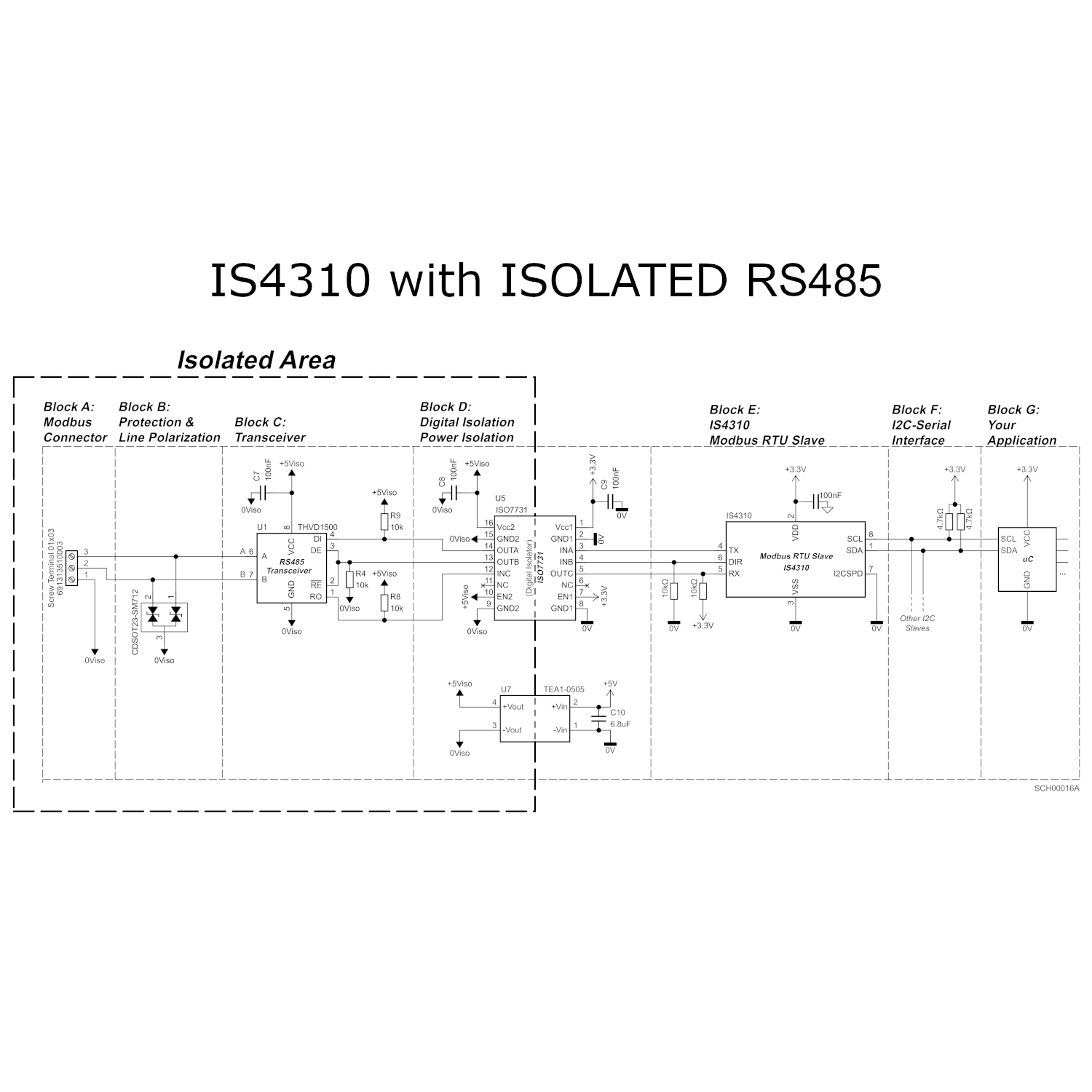
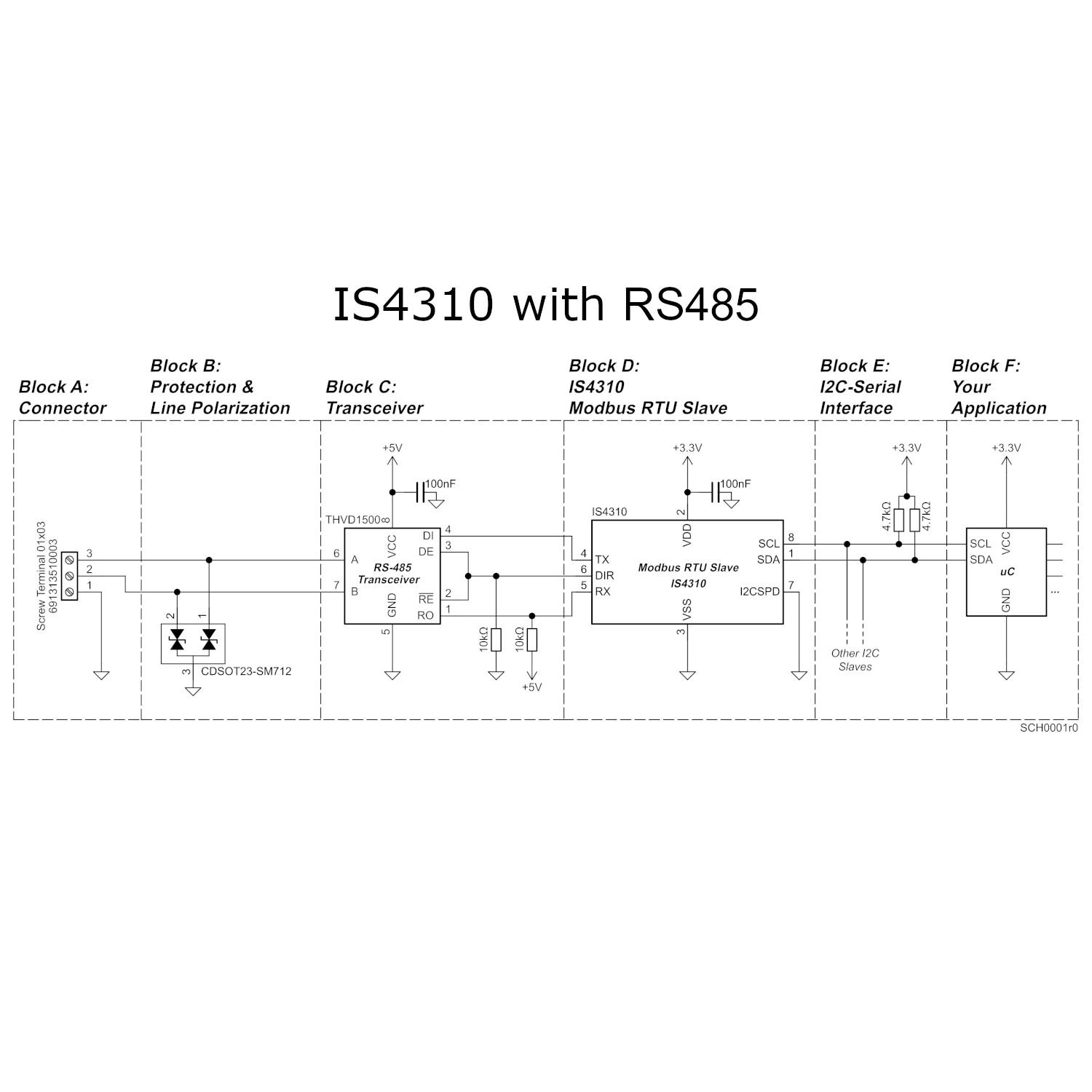
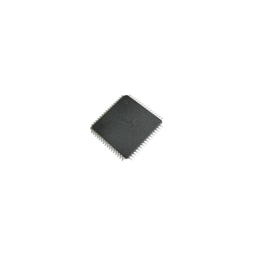
Do you prefer to integrate the Ethernet hardware on your own PCB? The IS4350 is also available as a chip in an LQFP64 package. It uses the same registers and the same I2C protocol, so your firmware works with both.
For the memory map, the I2C protocol, the I2C-CRC procedure and an Arduino example, see the IS4350 datasheet (ISDOC139).
This company and the products provided herein are developed independently and are not affiliated with, endorsed by, or associated with any official protocol or standardization entity. All trademarks, names, and references to specific protocols remain the property of their respective owners.
(This product includes the IS4350-M1 module. The 3.3 V power supply, the microcontroller and the Ethernet cable are not included.)