
Skip to main contentSkip to footer

RS232 Modbus RTU Slave Module: IS4310-232M5

RS232 Modbus RTU Slave with DB9 connector

500 Holding Registers for user data

Available Function Codes:
– 0x03 Read Holding Registers
– 0x06 Write Single Register
– 0x10 Write Multiple Registers

Default Modbus Settings:
– Modbus Slave ID: 1
– Modbus Baud Rate: 19200 bps
– Modbus Parity: Even
– Modbus Stop Bits: 1

I2C Characteristics:
– I2C Slave Address: 0x11 (fixed)
– I2C Speed: 100 kHz, 400 kHz, 1 MHz
– I2C Voltage: 3.3 V (5 V tolerant)

Power Supply: 3.3 V

Works with Arduino, STM32, Raspberry Pi or any microcontroller with I2C

In stock

SKU: IS4310-232M5

RS232 Modbus RTU Slave Module

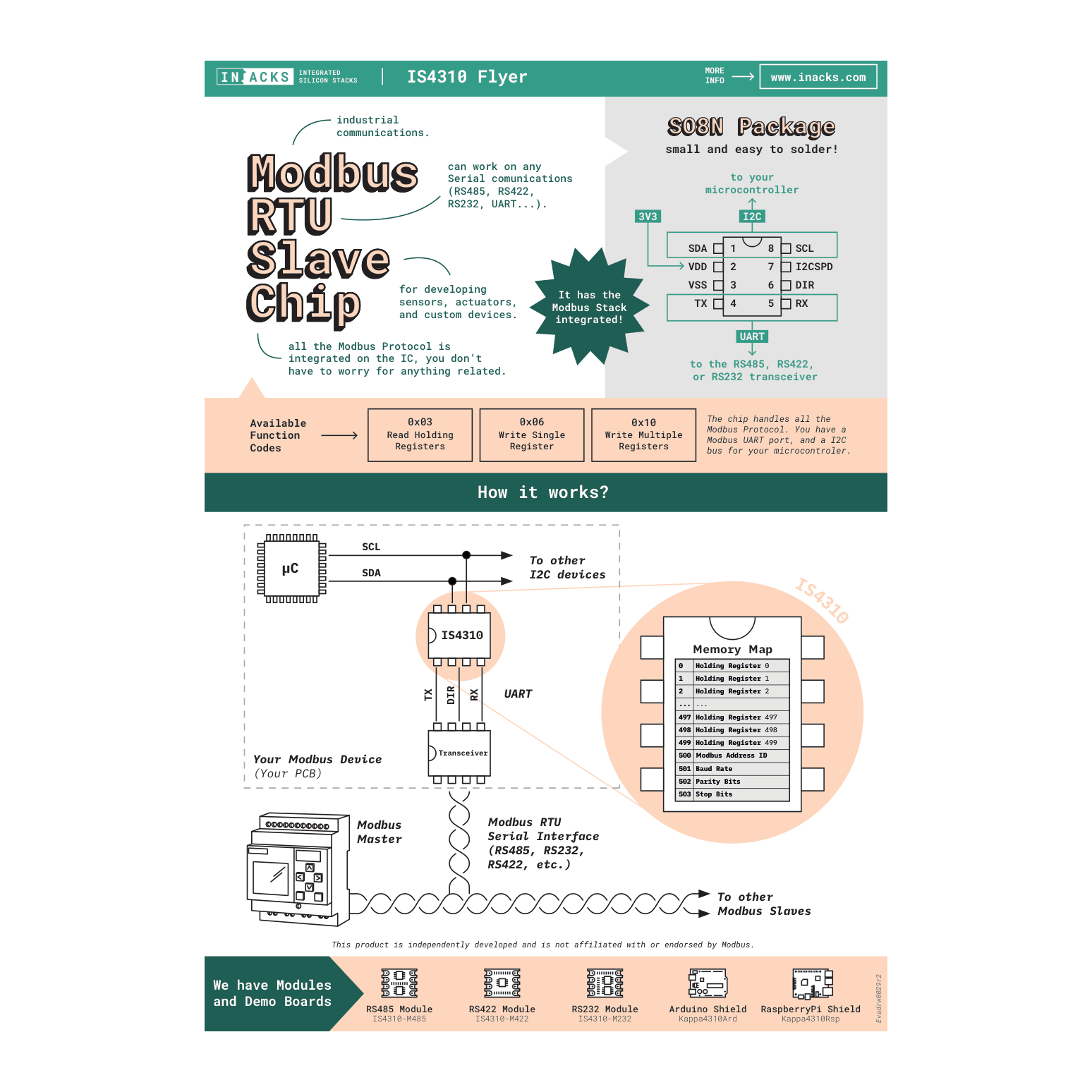
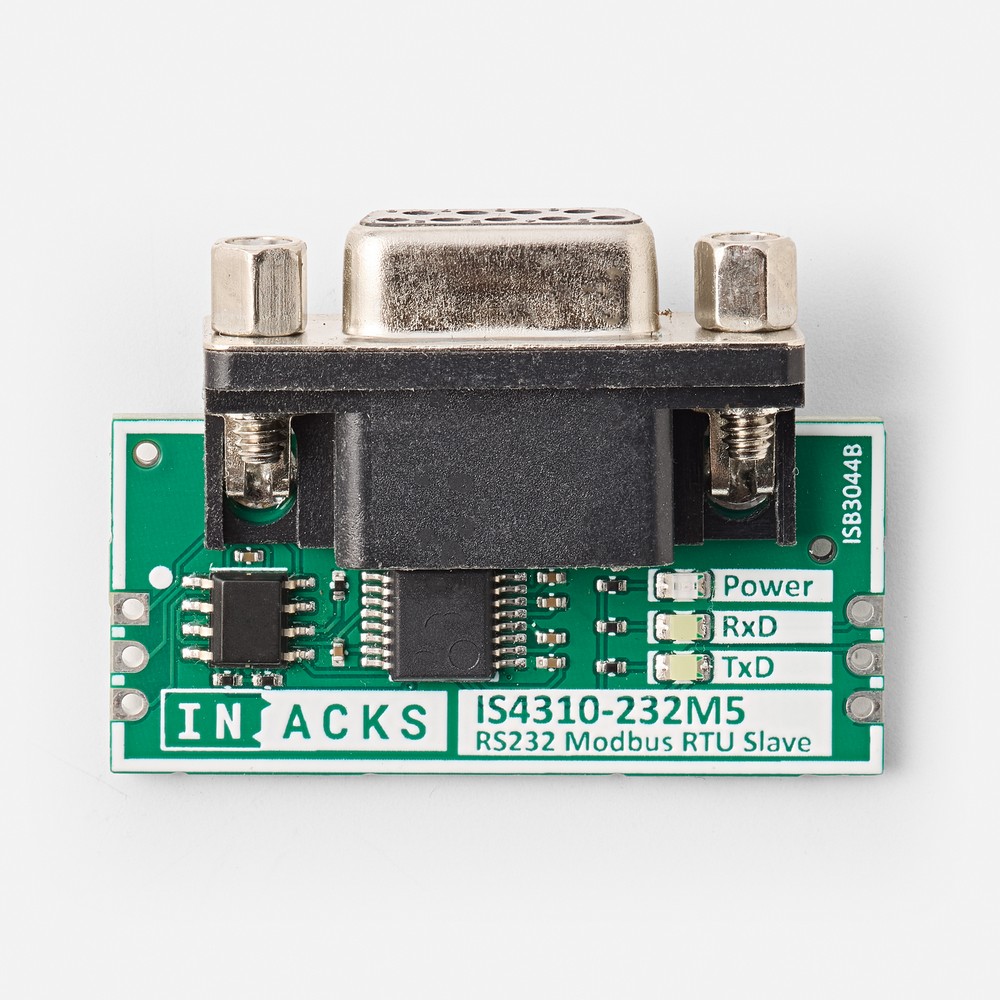
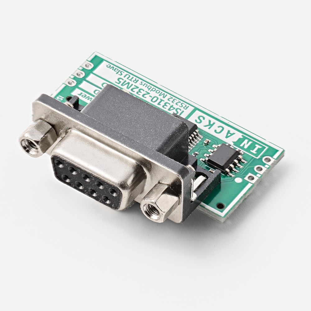
The IS4310-232M5 is an RS232 Modbus RTU Slave Module that integrates a Modbus RTU stack chip (IS4310), an RS232 transceiver and a female DB9 (DE-9) connector. It connects to the Modbus master with a standard straight-through (not crossed) DB9 cable.

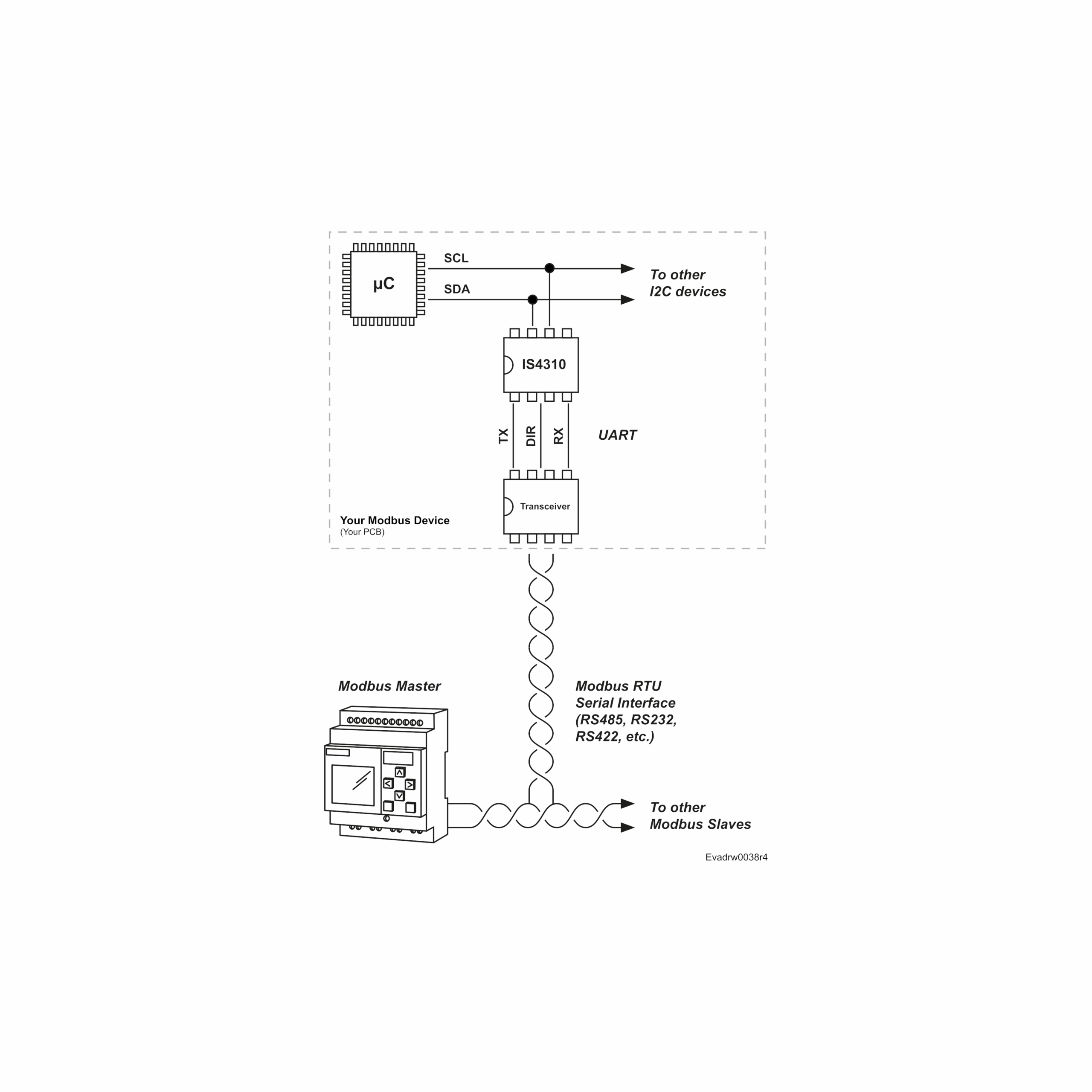
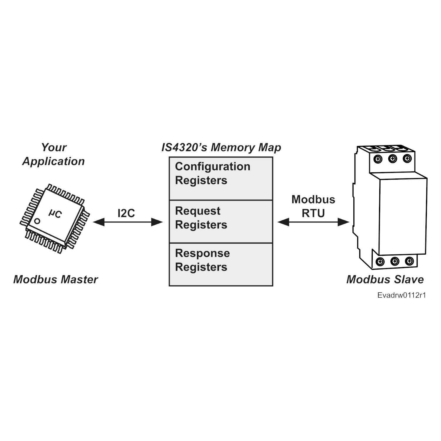
By integrating this module into your project, you instantly get a working Modbus RS232 interface. Just read from or write to the IS4310’s I2C memory registers, which directly map to the Modbus Holding Registers.

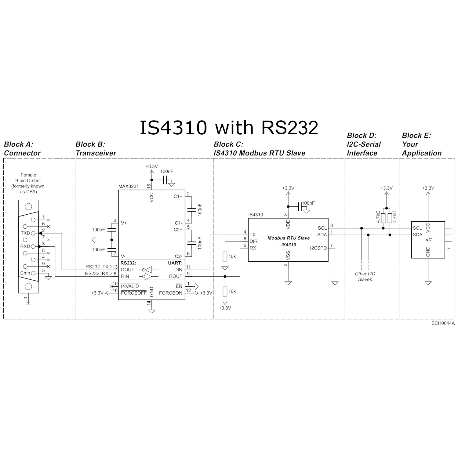
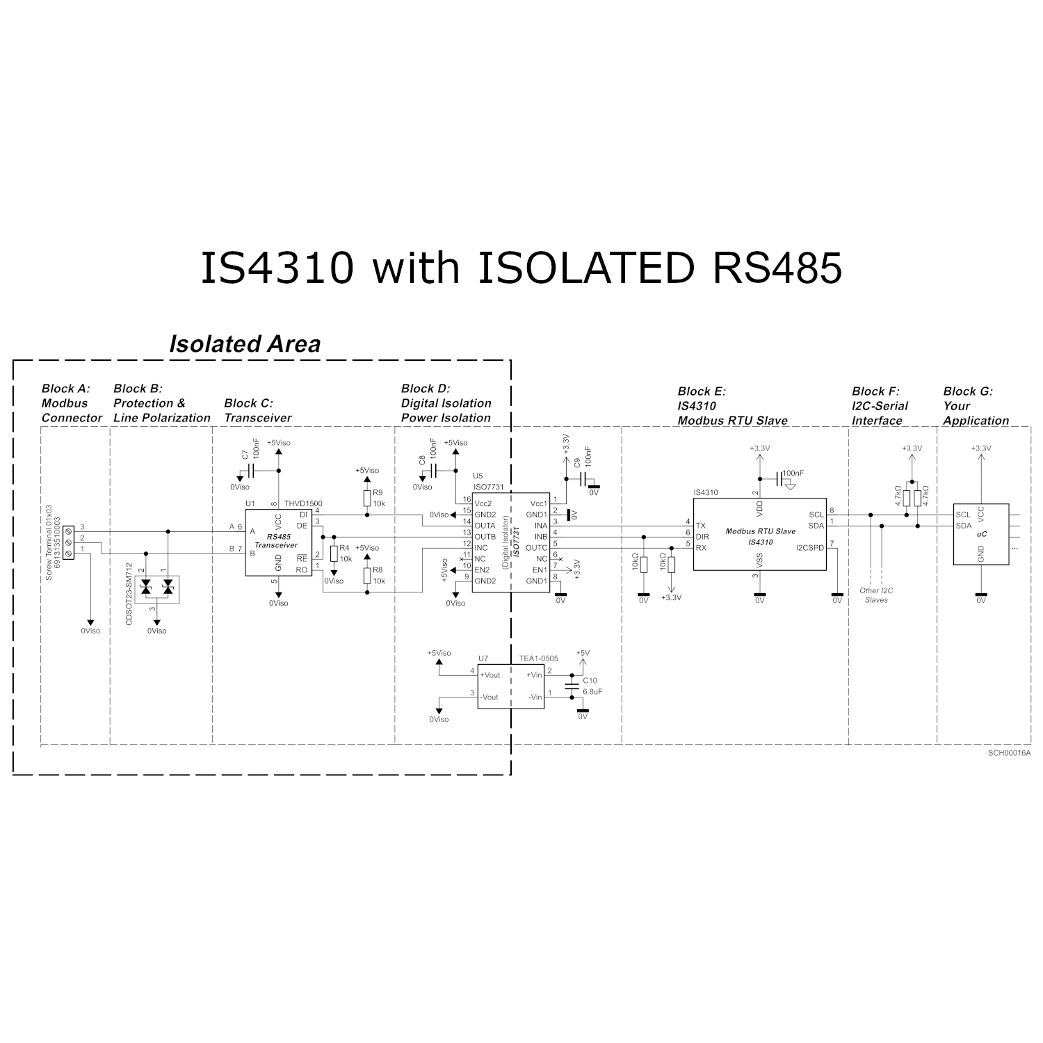
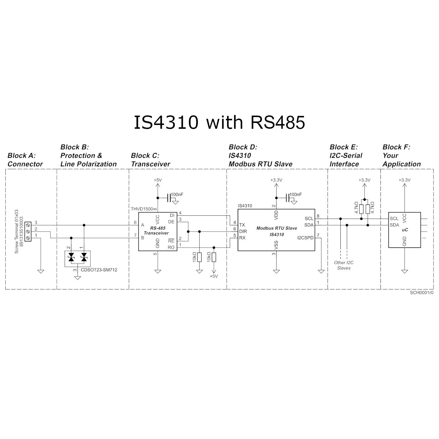
This solution minimizes the design effort required to integrate a Modbus RTU Slave with an RS232 physical layer. Optionally, you can integrate the IS4310 chip in your own design to minimize costs and customize the connector. Example schematics can be found in the IS4310 datasheet.

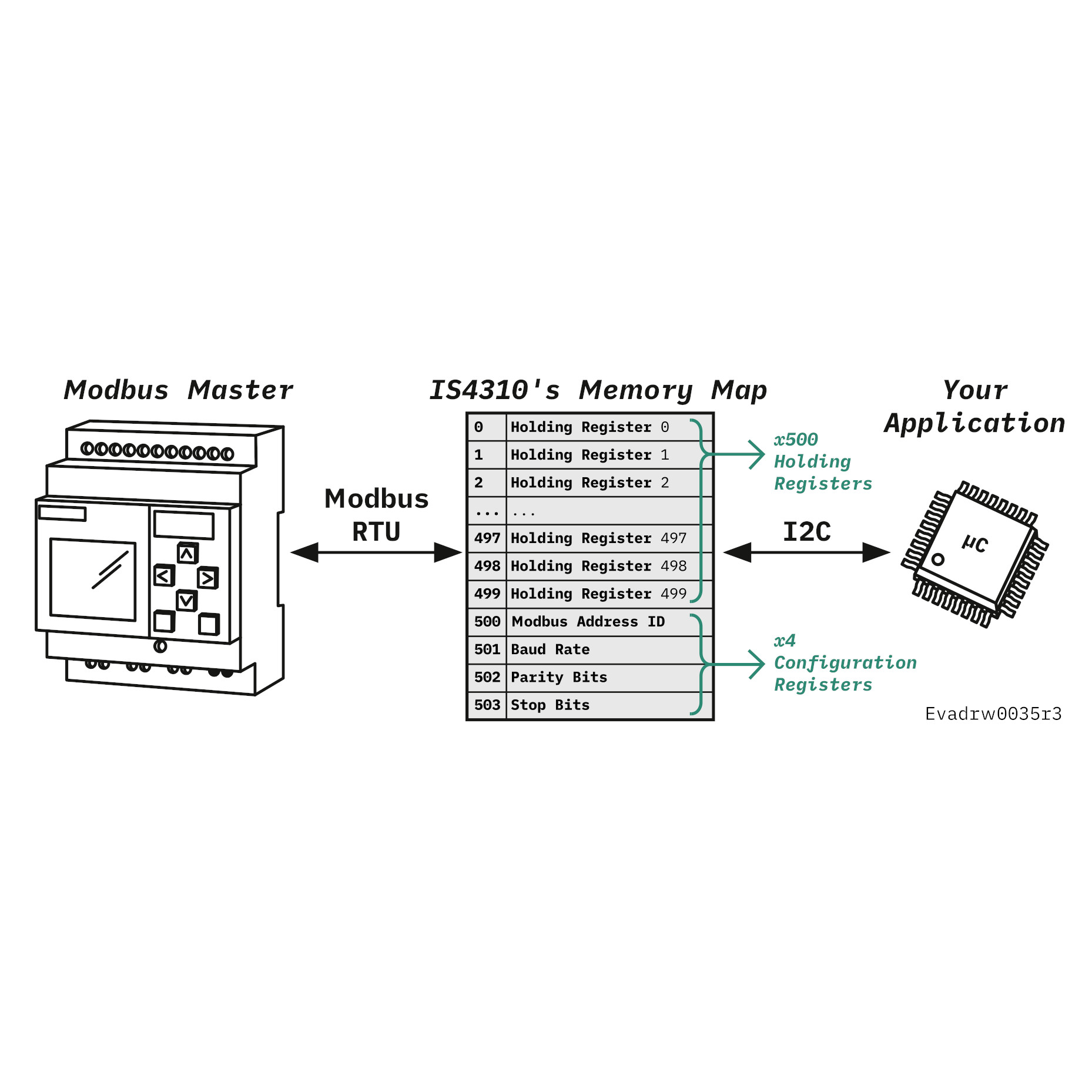
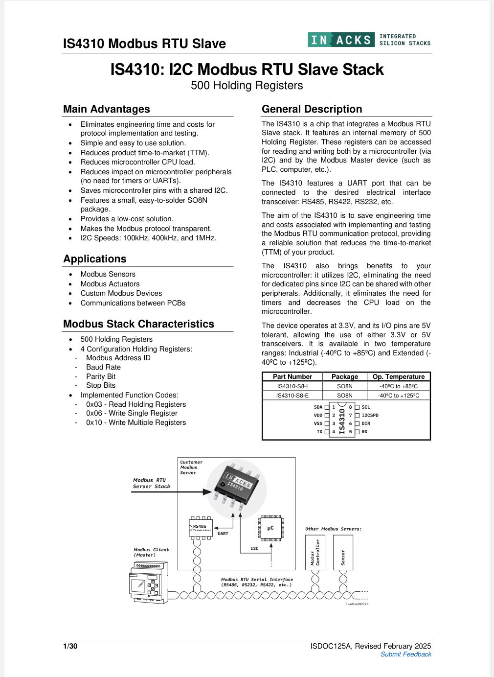
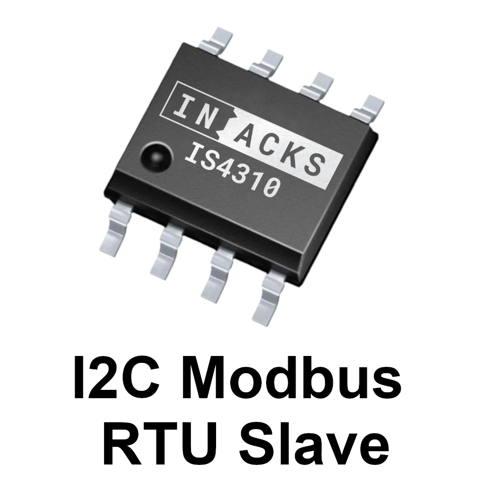
The IS4310 is a chip that integrates a Modbus RTU Slave stack. It features an internal memory of 500 Holding Registers, accessible by both a microcontroller (via I2C) and a Modbus Master device (e.g., PLC, HMI, computer, etc.).

You can use the IS4310 in three modes:

  • As a Sensor: your microcontroller writes data to the chip via I2C.
  • As an Actuator: your microcontroller reads data from the chip via I2C.
  • Mixed: your microcontroller reads and writes data to the chip via I2C.

Just read/write the registers you need. No protocol stack required.

The goal of the IS4310 is to eliminate the engineering effort typically required to implement and validate Modbus RTU communication. It offers a reliable, ready-to-use solution that helps reduce development time and speed up your time-to-market (TTM).


How Does the RS232 Modbus Module Work?

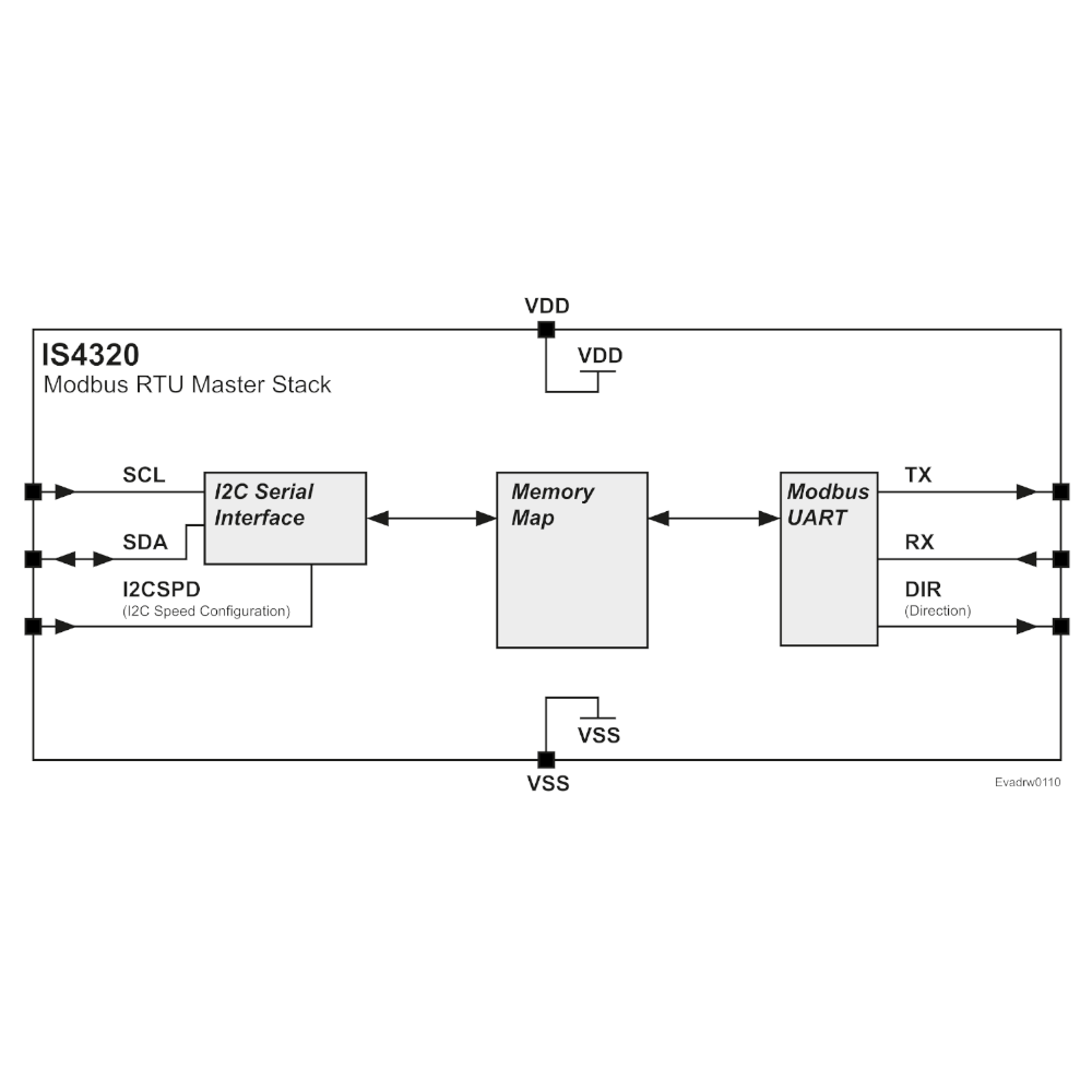
This RS232 Modbus RTU Slave Module provides two interfaces:

  • A castellated hole I2C interface for your microcontroller, FPGA, Arduino, Raspberry Pi, etc. This is where your system reads and writes Modbus data.
  • An RS232 DB9 connector, which connects the module to the Modbus master (a PC, PLC, HMI or any device with an RS232 port).

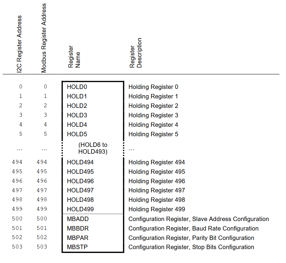
The internal memory is composed of 504 registers:

  • 500 Holding Registers for user data.
  • 4 Configuration Registers for communication settings: Modbus Slave ID, Baud Rate, Parity, Stop Bits.

The 500 Holding Registers are the key: whatever you write to them via I2C can be read by the RS232 master device. And vice versa: whatever the RS232 master device writes to them can be read by your microcontroller via I2C.

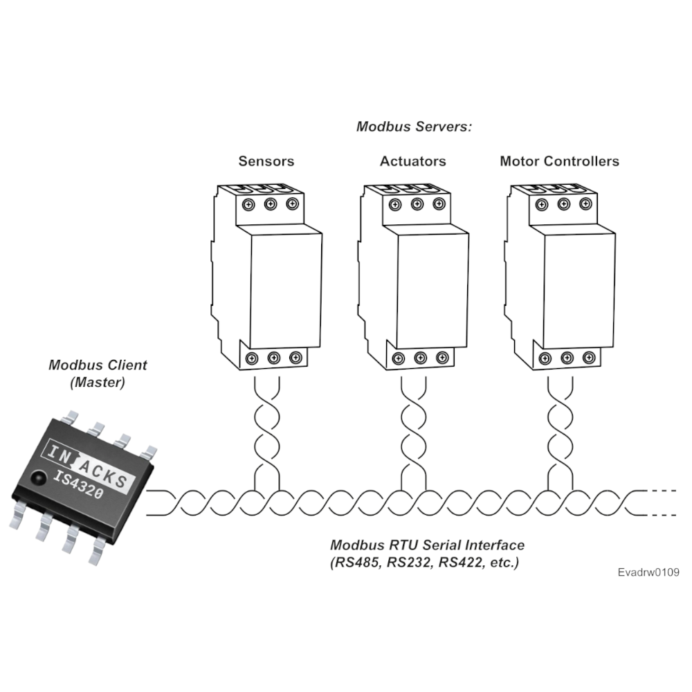
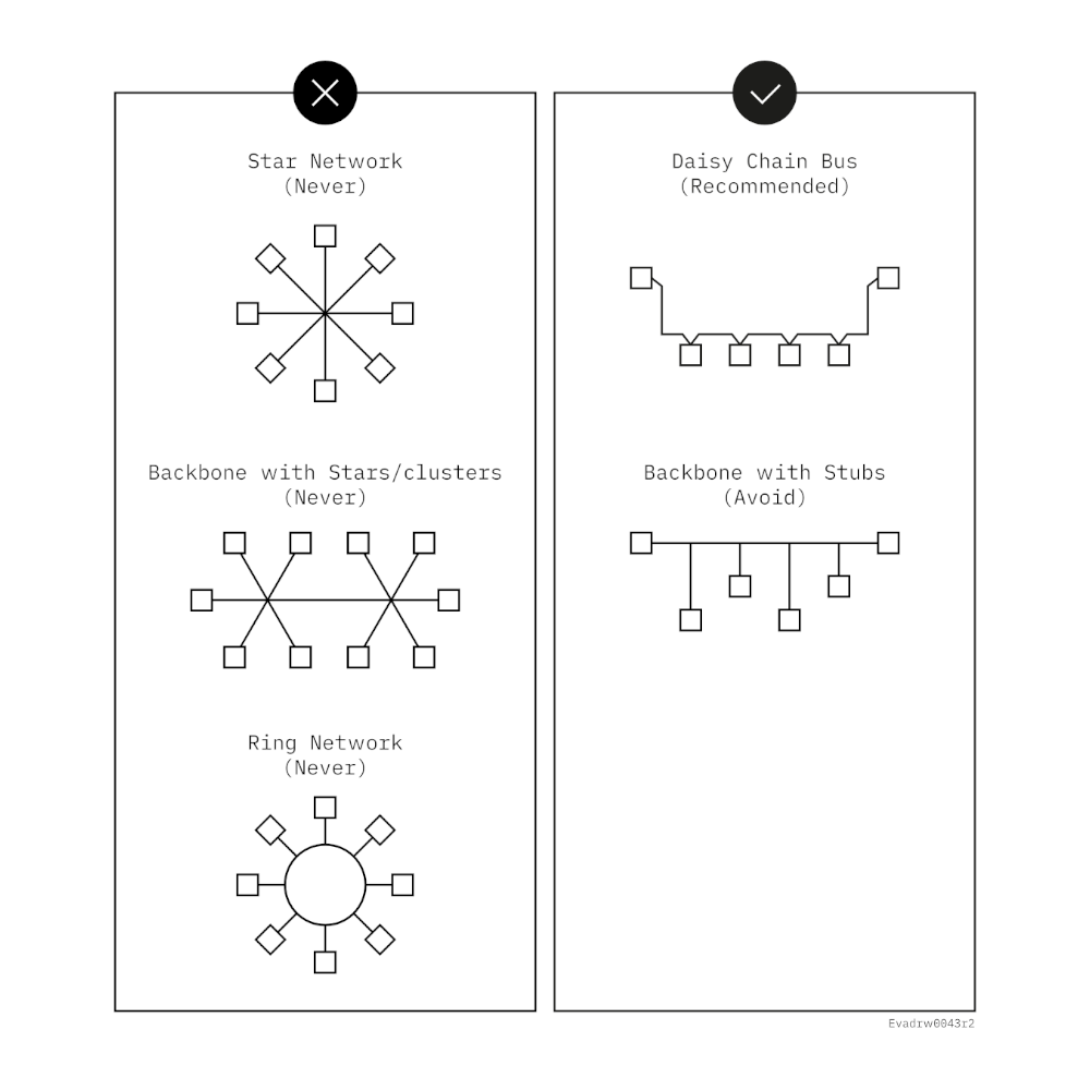
RS232 is a point-to-point link: one master and one slave. If you need several slaves on the same bus, use an RS485 module such as the IS4310-ISO485M6.


IS4310-232M5 Pinout

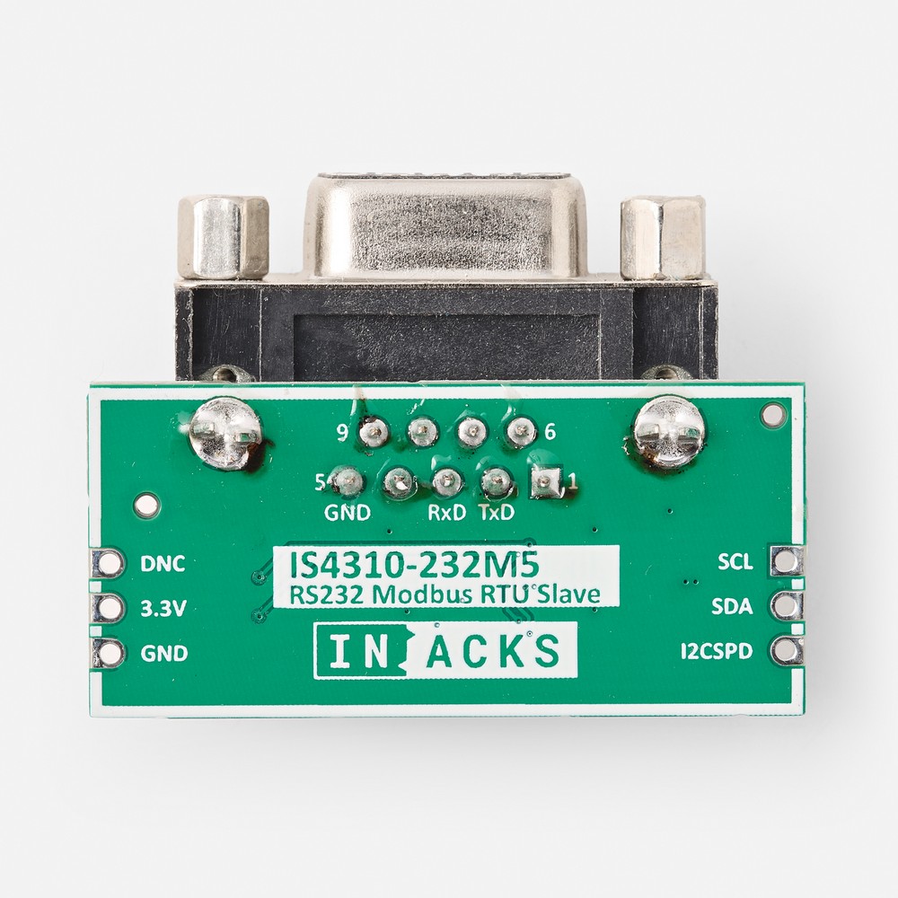
The module has six castellated pads, so you can solder it directly onto your PCB or use it with pin headers.

Pad Function
3.3V Power supply input (3.3 V).
GND Ground.
SDA I2C data. Open drain, 3.3 V (5 V tolerant). Needs a pull-up resistor.
SCL I2C clock. Open drain, 3.3 V (5 V tolerant). Needs a pull-up resistor.
I2CSPD I2C speed selection (see below). Never connect it to 5 V.
DNC Do not connect. Leave it floating.

DB9 connector (female): pin 2 = TxD, pin 3 = RxD, pin 5 = GND.


Default Module Settings

Default Modbus Settings:

  • Modbus Slave ID: 1
  • Modbus Baud Rate: 19200 bps
  • Modbus Parity: Even
  • Modbus Stop Bits: 1

Default I2C Settings:

  • I2C Slave Address: 0x11 (fixed)
  • I2C Speed: depends on the I2CSPD pin: 100 kHz (pin to GND), 400 kHz (pin to 3.3V/2), 1 MHz (pin to 3.3V)

Check the Examples tab for a super simple RS232 Modbus sensor built with a Raspberry Pi.
Q: What is the IS4310-232M5?

A: An RS232 Modbus RTU Slave Module. It combines the IS4310 Modbus RTU Slave chip, an RS232 transceiver and a female DB9 connector. Your microcontroller reads and writes 500 Holding Registers via I2C, and the Modbus master reads and writes the same registers over RS232.

Q: Do I need a Modbus library or protocol stack?

A: No. The IS4310 handles the Modbus RTU protocol. Your code only reads and writes registers via I2C, with the standard I2C driver of your platform: Wire on Arduino, HAL on STM32 or smbus2 on Raspberry Pi.

Q: Which Modbus function codes are supported?

A: 0x03 Read Holding Registers, 0x06 Write Single Register and 0x10 Write Multiple Registers.

Q: What are the default Modbus settings?

A: Slave ID 1, 19200 bps, Even parity and 1 stop bit. You can change them through the 4 Configuration Registers.

Q: Which cable do I need?

A: A standard straight-through (not crossed) DB9 cable. You can also plug a USB to RS232 adapter directly into the DB9 connector of the module.

Q: Can I connect several slaves to the same RS232 port?

A: No. RS232 is a point-to-point link: one master and one slave. For a bus with several slaves, use an RS485 module such as the IS4310-ISO485M6.

Q: What supply voltage does it need?

A: 3.3 V. The I2C pins are 5 V tolerant, so you can also use the module with 5 V microcontrollers.

Q: How do I select the I2C speed?

A: With the I2CSPD pin: GND for 100 kHz, 3.3V/2 for 400 kHz and 3.3V for 1 MHz. The selected speed must match the speed of your I2C bus. Never connect this pin to 5 V.

Q: Does it work with a Raspberry Pi?

A: Yes. Connect 3.3V, GND, SDA and SCL to the Raspberry Pi header and tie I2CSPD to GND (100 kHz). The Examples tab includes a simple Python example that turns the Pi into an RS232 Modbus sensor.

Q: Can I use the IS4310 chip in my own PCB?

A: Yes. The IS4310 is also available as a standalone chip, and its datasheet includes example schematics.

RS232 Modbus Sensor with Raspberry Pi

This super simple example turns a Raspberry Pi into an RS232 Modbus RTU sensor. The Pi measures its own CPU temperature and writes it to Holding Register 0 of the IS4310-232M5. No extra sensor is needed.

1. Wiring

IS4310-232M5 pad Raspberry Pi pin
3.3V Pin 1 (3.3V)
GND Pin 6 (GND)
SDA Pin 3 (GPIO2 / SDA)
SCL Pin 5 (GPIO3 / SCL)
I2CSPD Pin 9 (GND), for 100 kHz
DNC Not connected

The Raspberry Pi already has pull-up resistors on SDA and SCL, so no extra components are needed. On the RS232 side, plug a USB to RS232 adapter into the DB9 connector, or use a straight-through DB9 cable to the RS232 port of your PC or PLC.

2. Code

Enable I2C with sudo raspi-config (Interface Options > I2C), install the library with sudo apt install python3-smbus2, and save this script as rs232_modbus_sensor.py:

# IS4310-232M5 example: RS232 Modbus RTU sensor with a Raspberry Pi
#
# The Raspberry Pi measures its CPU temperature and writes it to
# Holding Register 0 of the IS4310 via I2C. Any Modbus RTU master
# connected to the DB9 port can read it.
#
# Modbus settings: Slave ID 1, 19200 bps, Even parity, 1 stop bit.
# Install: sudo apt install python3-smbus2
# Run:     python3 rs232_modbus_sensor.py

import time
from smbus2 import SMBus, i2c_msg

IS4310_I2C_ADDRESS = 0x11  # Fixed I2C address of the IS4310


def write_holding_register(bus, register, value):
    # Send the 16-bit register address and the 16-bit value, high byte first
    data = [register >> 8, register & 0xFF, value >> 8, value & 0xFF]
    bus.i2c_rdwr(i2c_msg.write(IS4310_I2C_ADDRESS, data))


def read_cpu_temperature():
    # Linux reports millidegrees (48312 = 48.312 °C). Return tenths of °C (483).
    with open("/sys/class/thermal/thermal_zone0/temp") as f:
        return int(f.read()) // 100


with SMBus(1) as bus:  # I2C bus 1: GPIO2 (SDA) and GPIO3 (SCL)
    while True:
        temperature = read_cpu_temperature()
        write_holding_register(bus, 0, temperature)
        print(f"CPU temperature: {temperature / 10:.1f} °C -> Holding Register 0 = {temperature}")
        time.sleep(1)

Run it with python3 rs232_modbus_sensor.py. Every second, it prints the temperature and writes it to Holding Register 0.

3. Read the Sensor from Your PC

Open a Modbus RTU master such as qModMaster and select the COM port of your RS232 adapter with these settings: Slave ID 1, 19200 bps, 8 data bits, Even parity, 1 stop bit. Then read Holding Register 0 with function code 0x03. A value of 483 means 48.3 °C.

Tip: if the master gets no answer, run i2cdetect -y 1 on the Pi. The module must appear at address 11.

More IS4310 examples for Arduino, STM32 and Raspberry Pi are listed in the Documentation tab.

Evaluation boards, Modules & other related products

Evaluation boards, modules, and accessories designed for fast prototyping and easy integration. Featuring standard interfaces and built-in transceivers, they simplify testing and development across platforms like Arduino, Nucleo, or Raspberry Pi. Ideal for adding RS485, RS232, or Ethernet functionality with minimal effort and maximum compatibility.

Have a question?

Fill out this field
Please enter a valid email address.
Fill out this field
You need to agree with the terms to proceed