
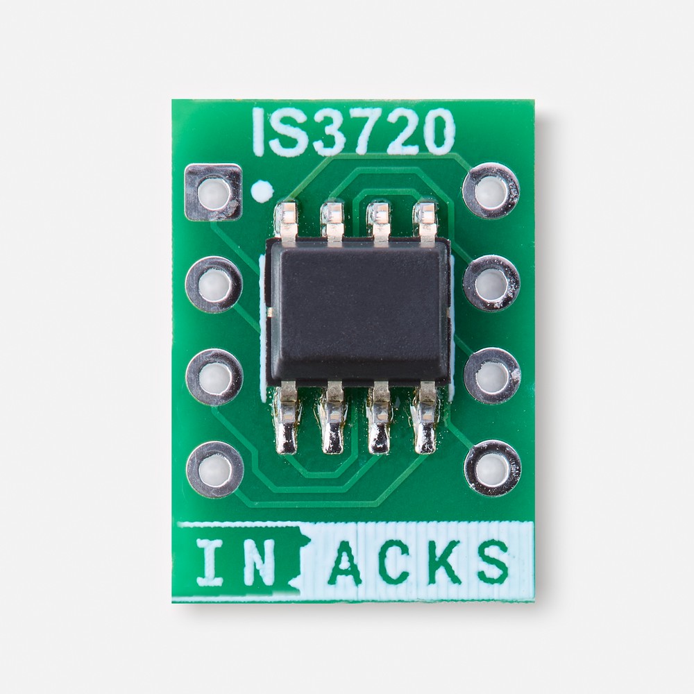
What is the IS3720 RDM responder chip?
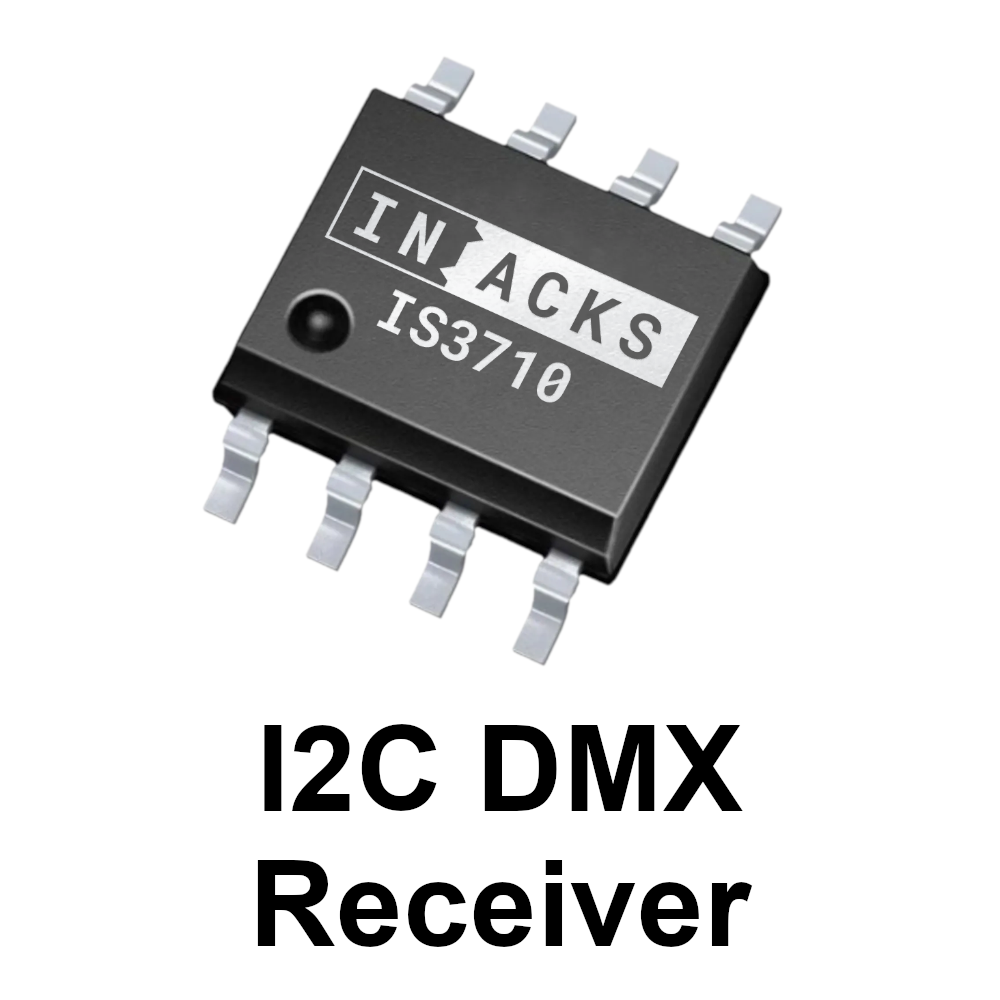
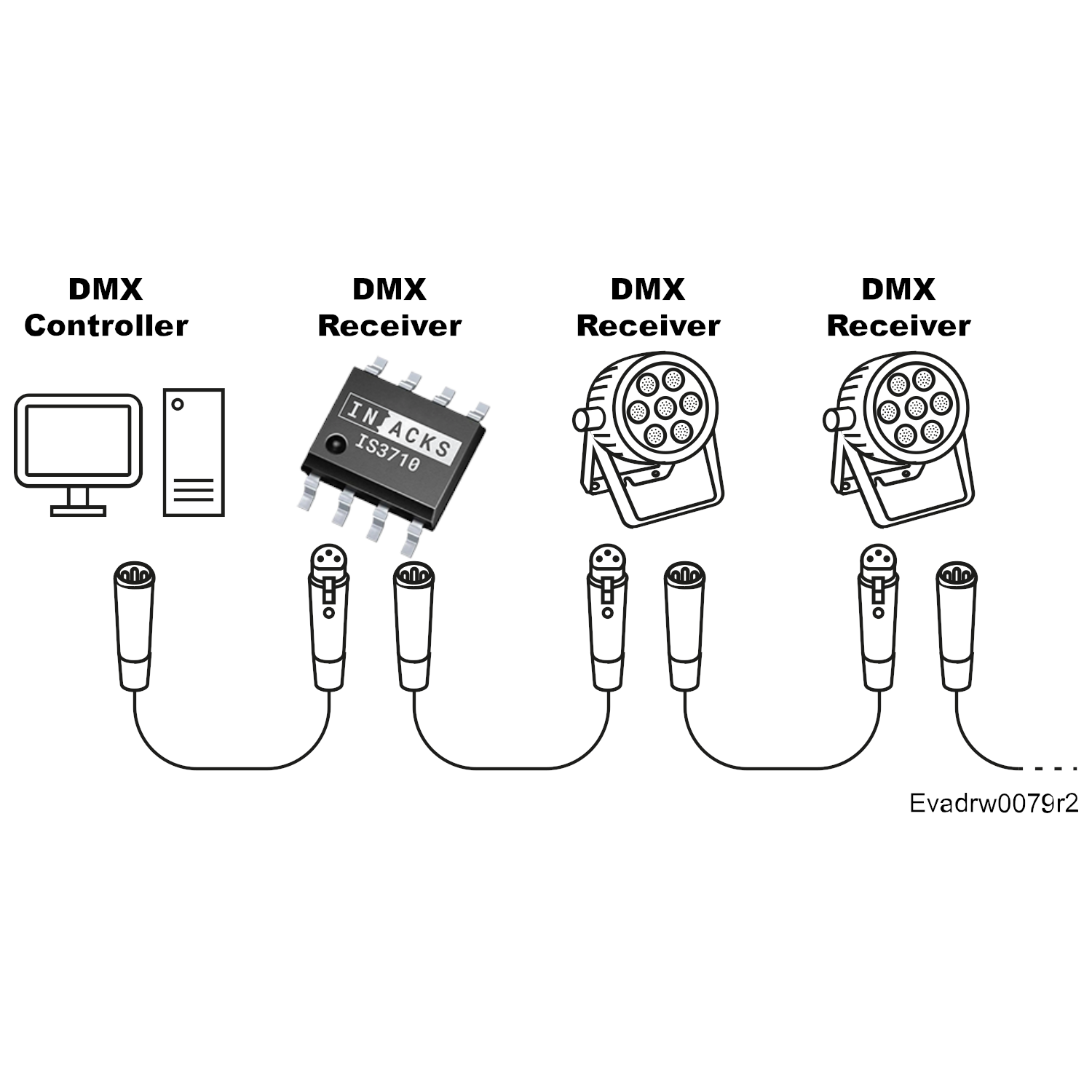
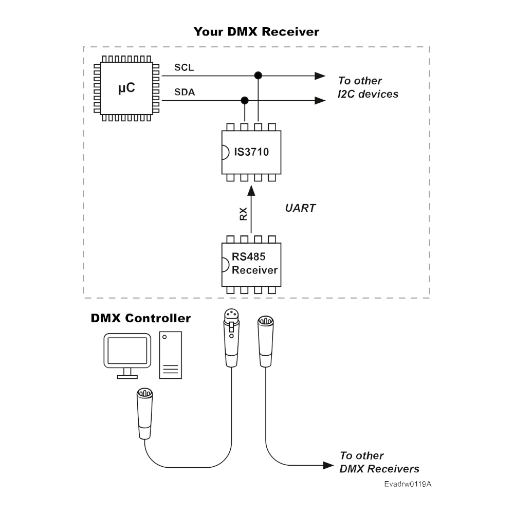
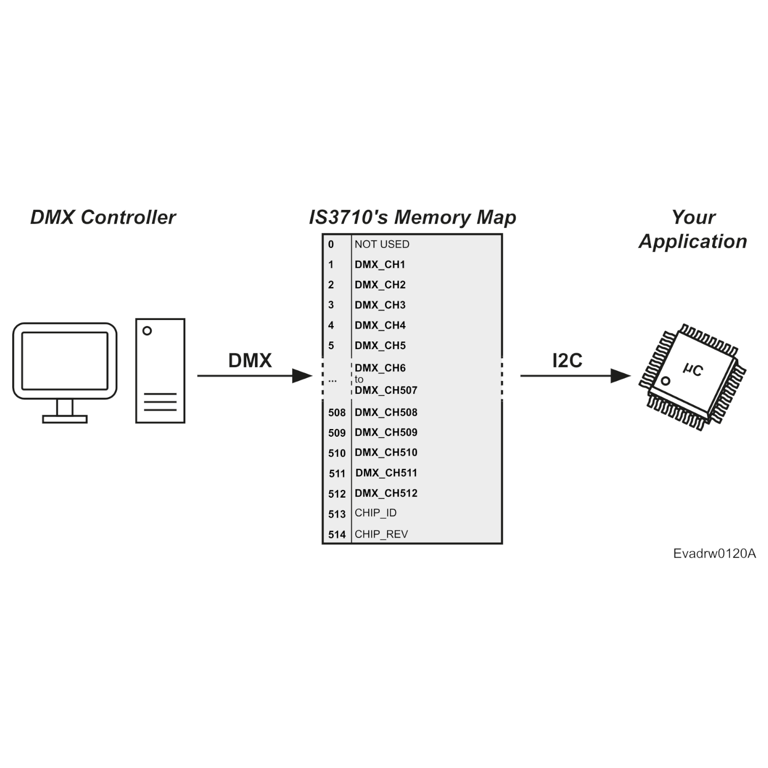
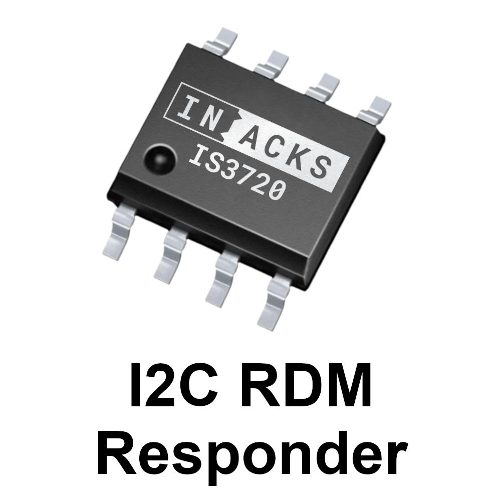
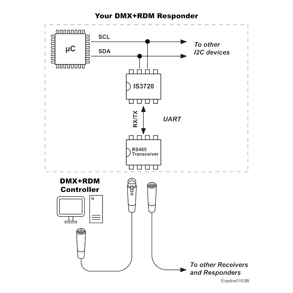
The IS3720 is an RDM responder chip with a built-in DMX512 receiver. It continuously buffers all 512 DMX channels in an internal register map that your microcontroller reads over I2C.
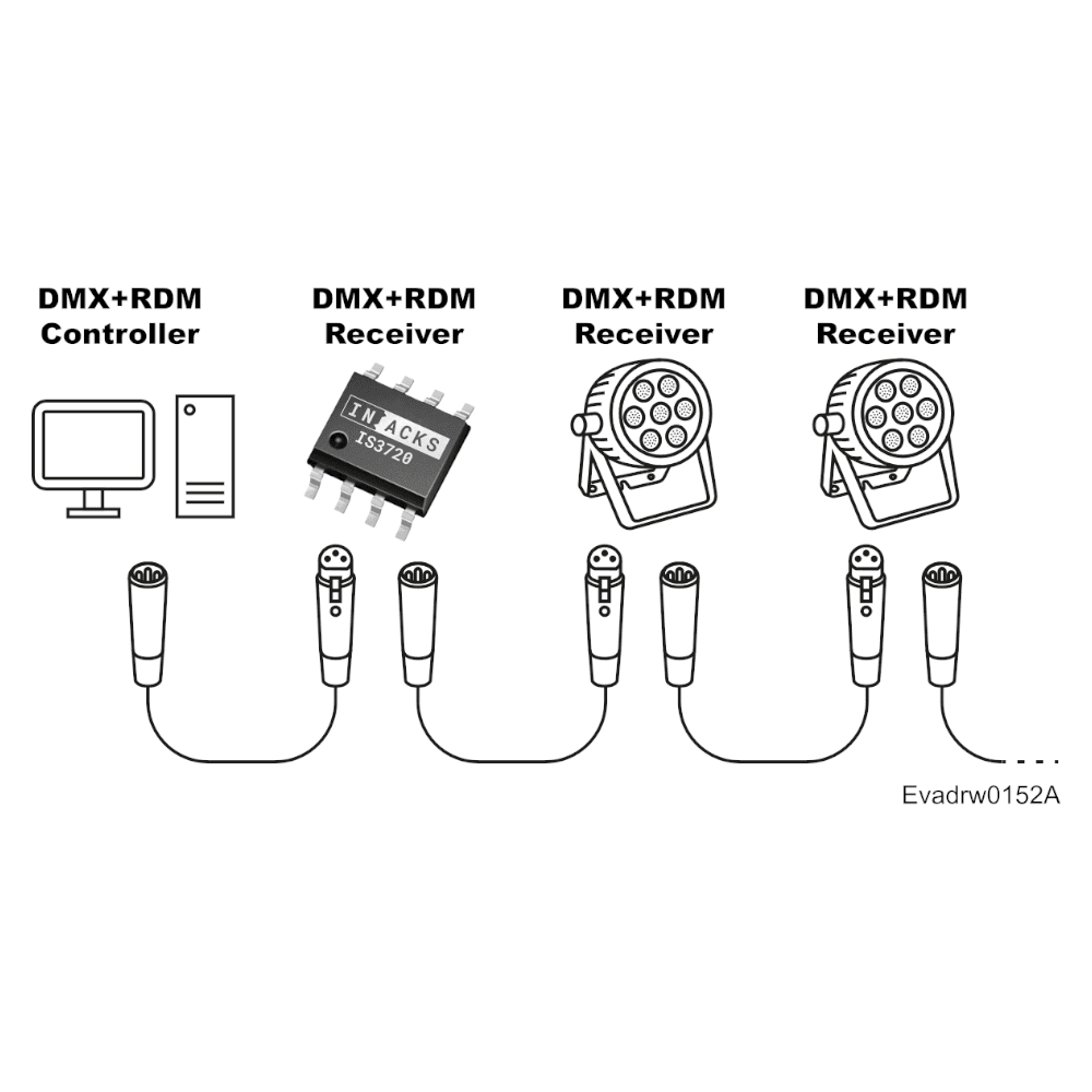
The IS3720 also answers the RDM controller on its own: discovery, device information, labels, DMX start address and identify requests. Lighting operators can find, address and identify your product remotely, without DIP switches or opening the fixture.
Documentation
- Download IS3720 Datasheet
- IS3720 Arduino Firmware Example
- Evaluation boards: Kappa3720Ard (Arduino) and Kappa3720Rasp (Raspberry Pi)
Your brand on every RDM controller
Your firmware writes your company name, model name and number, software version and product category into the IS3720 over I2C. From then on, RDM controllers display your product, not the chip.
These settings live in non-volatile memory and are only rewritten when a value changes, so your firmware can safely write them at every startup.
Utility
RDM is especially helpful for light fixtures in large installations, such as building façade lighting. There, an operator would otherwise spend significant time setting DIP switches on thousands of fixtures across multiple floors and rooms.
It is also invaluable for fixtures embedded in pavement or other sealed environments, like swimming pools and ornamental fountains. Opening those means breaking the ground or compromising waterproofing. Because the IS3720 also reports your DMX footprint, RDM controllers can auto-patch your fixtures.
Why use an RDM responder chip
It moves the whole protocol off your microcontroller:
- No low-level DMX or RDM details to learn, implement or debug; the IS3720 handles the timing.
- Fewer ISRs and lower CPU load, with no UART or timers dedicated to DMX.
- Less flash and RAM, and only two I2C pins (plus an optional INT pin).
- Less development and testing effort, and a faster time to market.
How the IS3720 RDM responder chip works
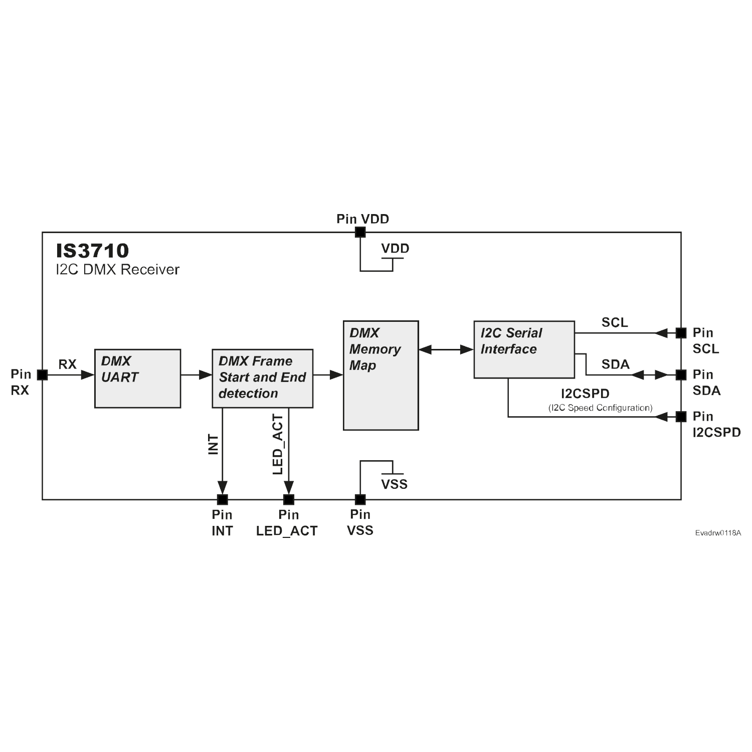
The IS3720 has two communication interfaces:
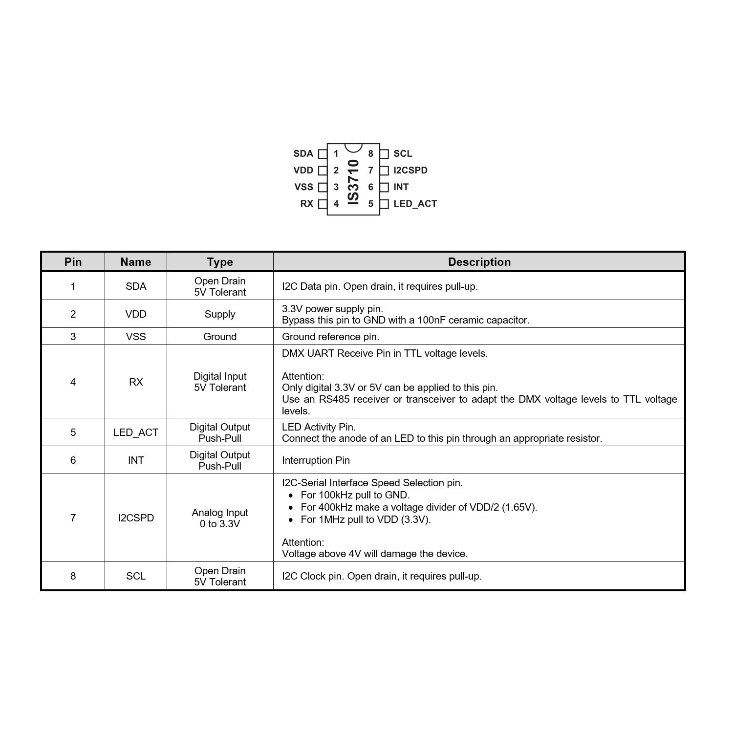
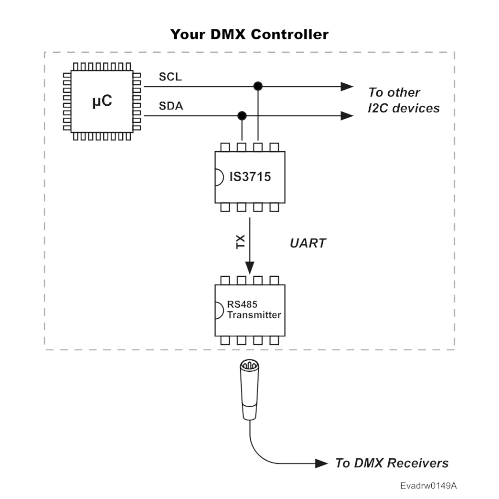
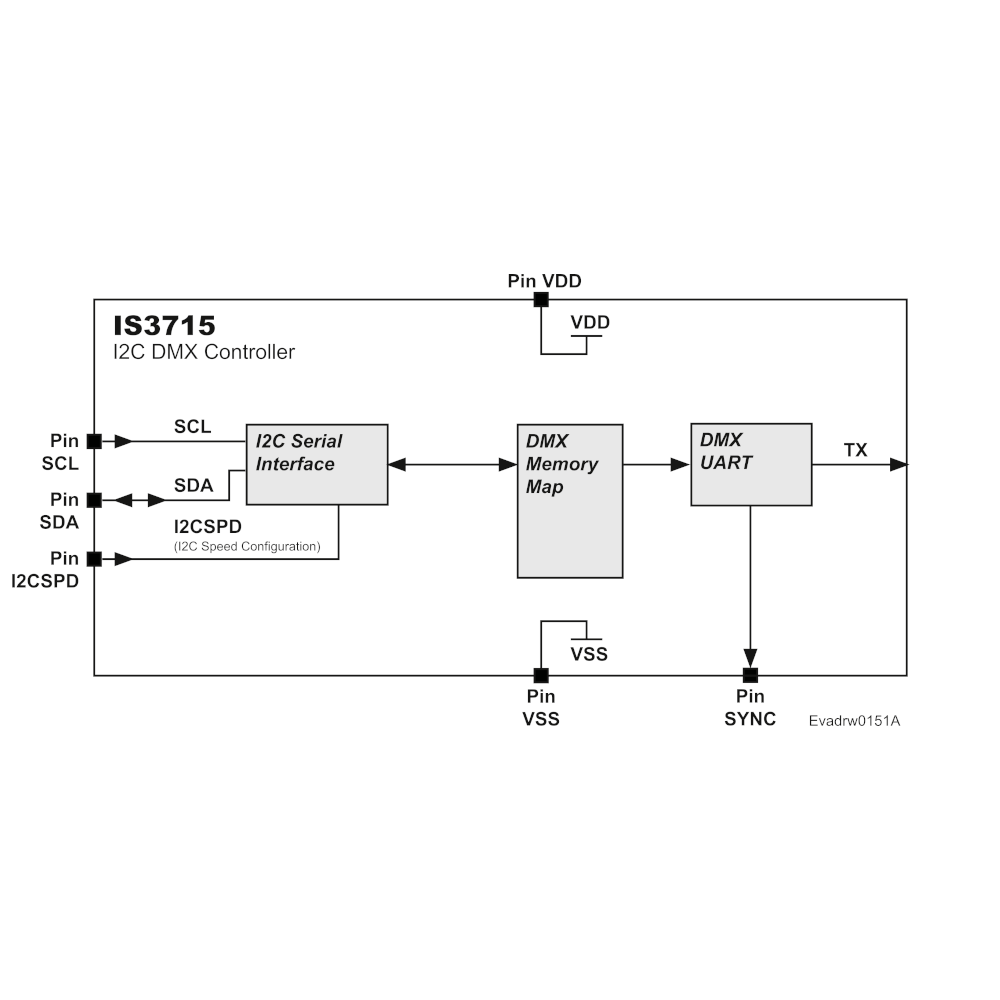
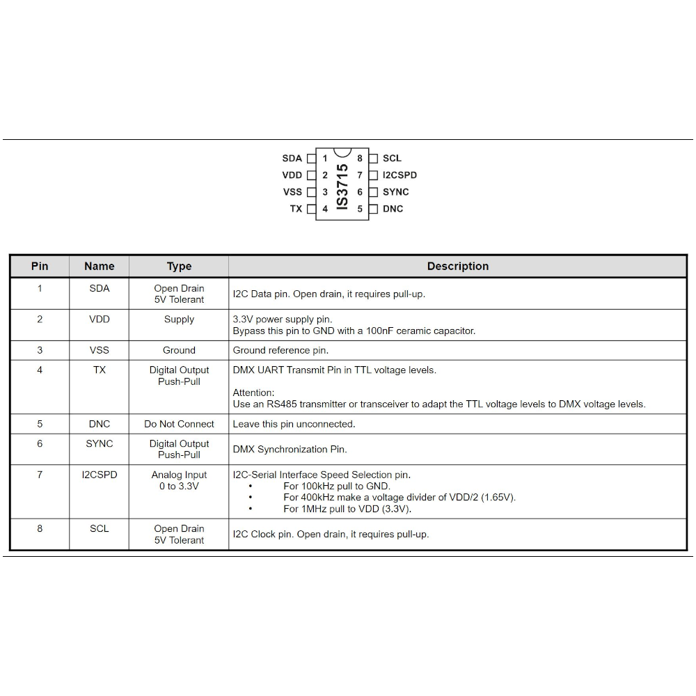
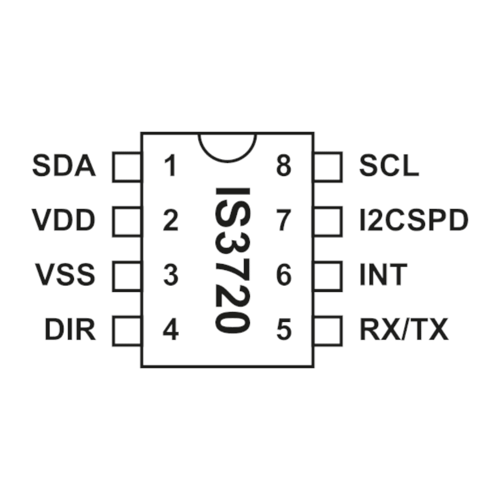
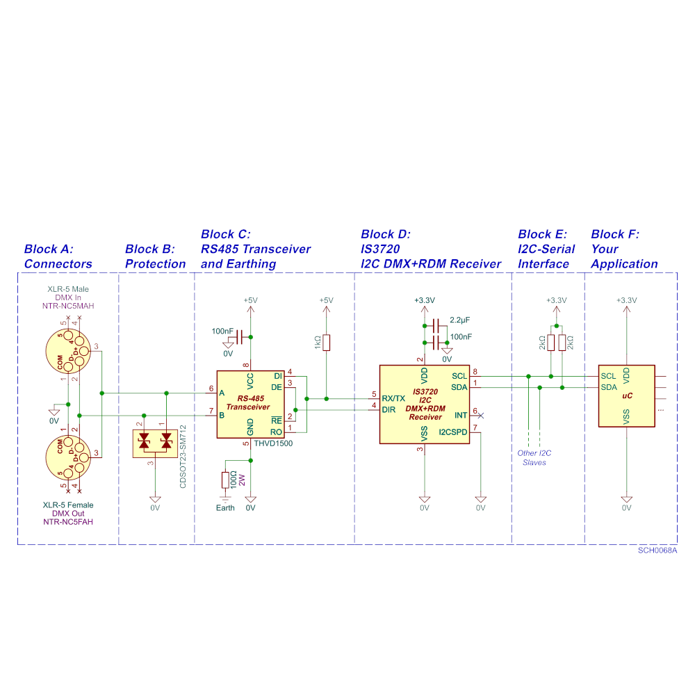
- I2C (SCL, SDA) to your microcontroller: slave address 22 (0x16), 16-bit register addressing, and 100 kHz, 400 kHz or 1 MHz selected with the I2CSPD pin. The I2C master must support clock stretching.
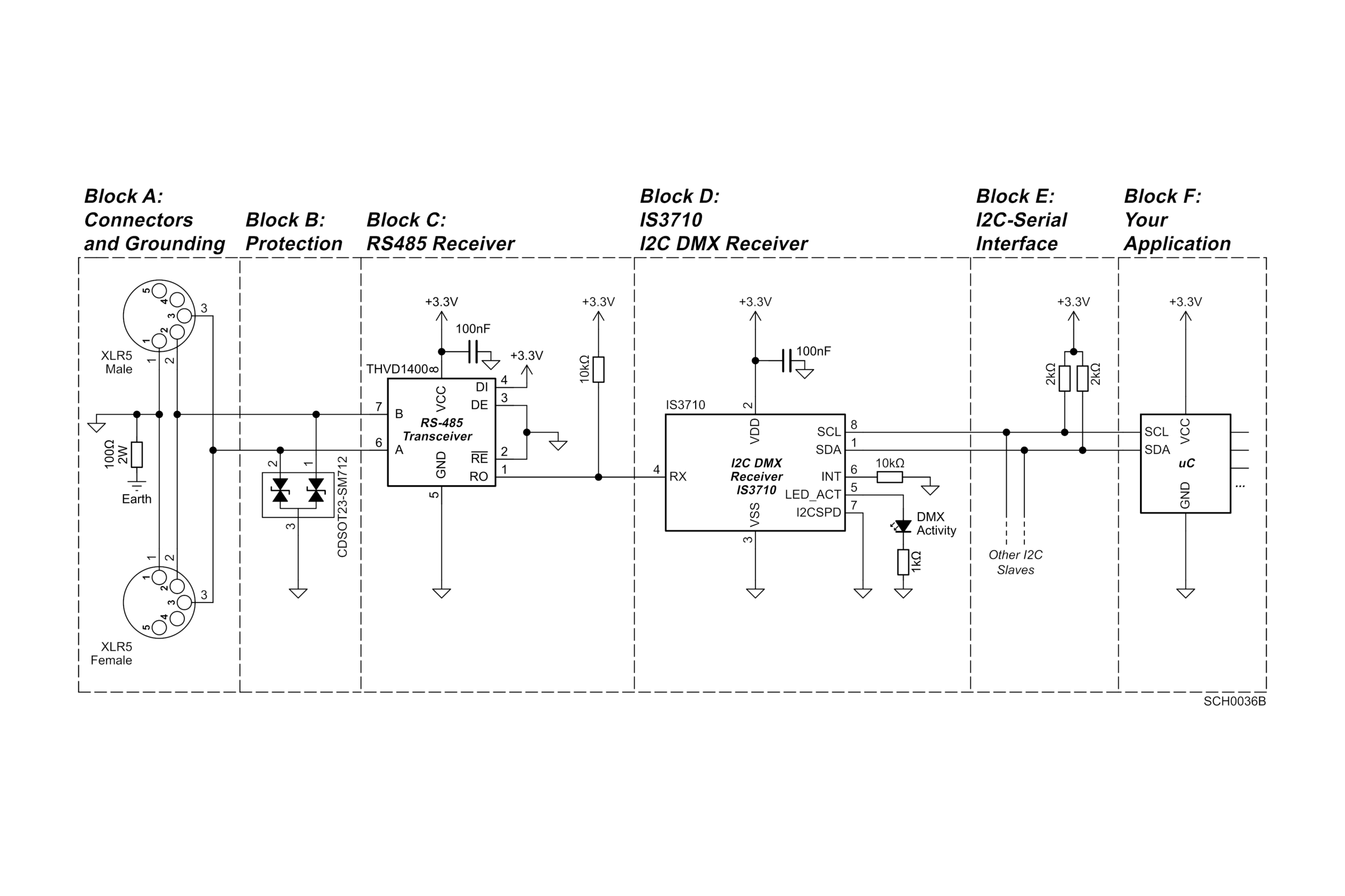
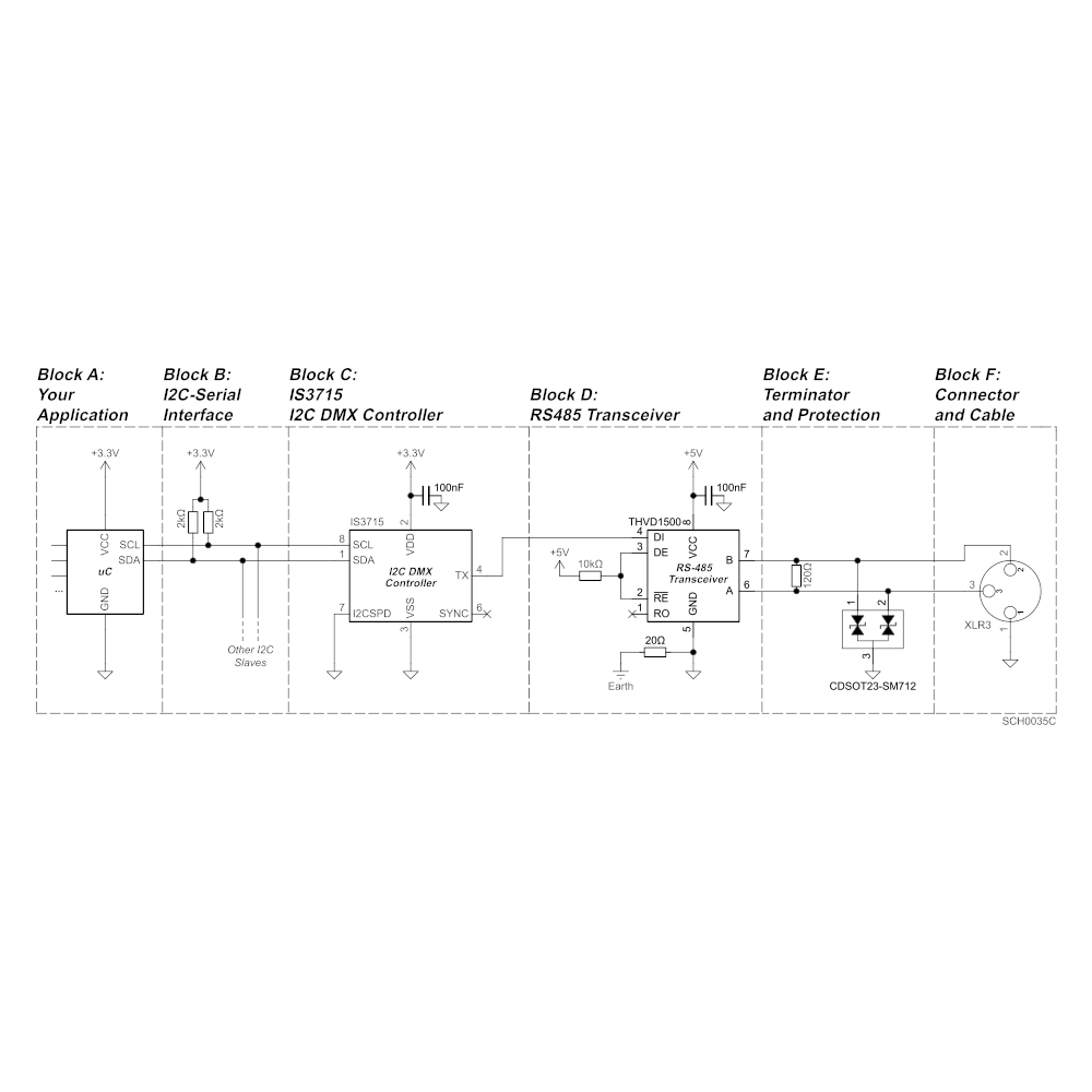
- UART (RX/TX, DIR) to an external RS485 transceiver such as the THVD1500, carrying the half-duplex DMX+RDM link. Both pins are open-drain and 5 V-tolerant, with pull-up resistors to the transceiver supply.
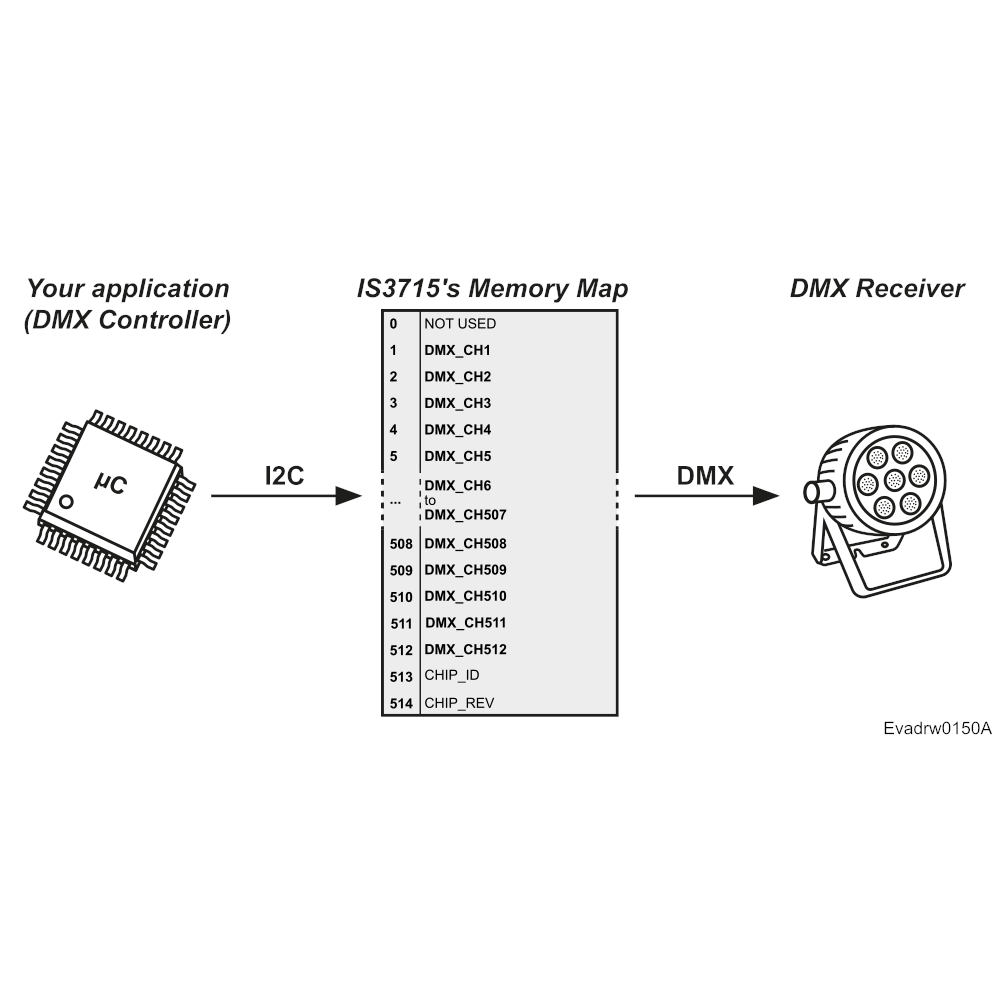
The internal memory map holds 632 8-bit registers. Registers 1 to 512 hold DMX channels 1 to 512: reading register 1 returns channel 1, and reading register 512 returns channel 512.
The RDM registers follow. Some are informational, such as MANUFACTURER_LBL, where you write your company name. Others are operational, such as DMX_START_ADDRESS, which tells your firmware the start address set by the operator.
The INT pin pulses whenever the DMX start address or the identify state changes, so your firmware doesn’t need to poll them.
Firmware in three steps
- At startup, write your product category, DMX footprint and labels over I2C, plus the UID if your firmware holds a unique one per unit.
- Write 1 to RDM_ONLINE to bring RDM online. DMX reception is always active.
- In the main loop, read DMX_START_ADDRESS and the channels your fixture uses, and run your identify pattern while IDENTIFY_DEVICE is 1.
From prototype to production
- Each IS3720 ships with a prototyping UID. For commercial products, program your own ESTA manufacturer ID and serial numbers.
- On the production line, a provisioning PID lets you write a unique UID to each unit over RDM.
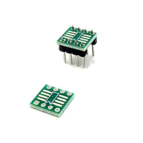
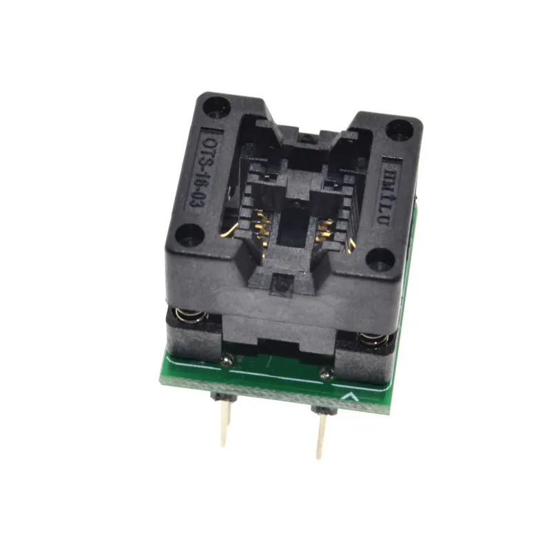
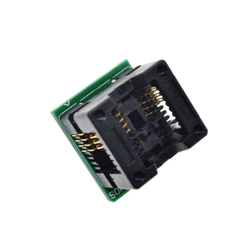
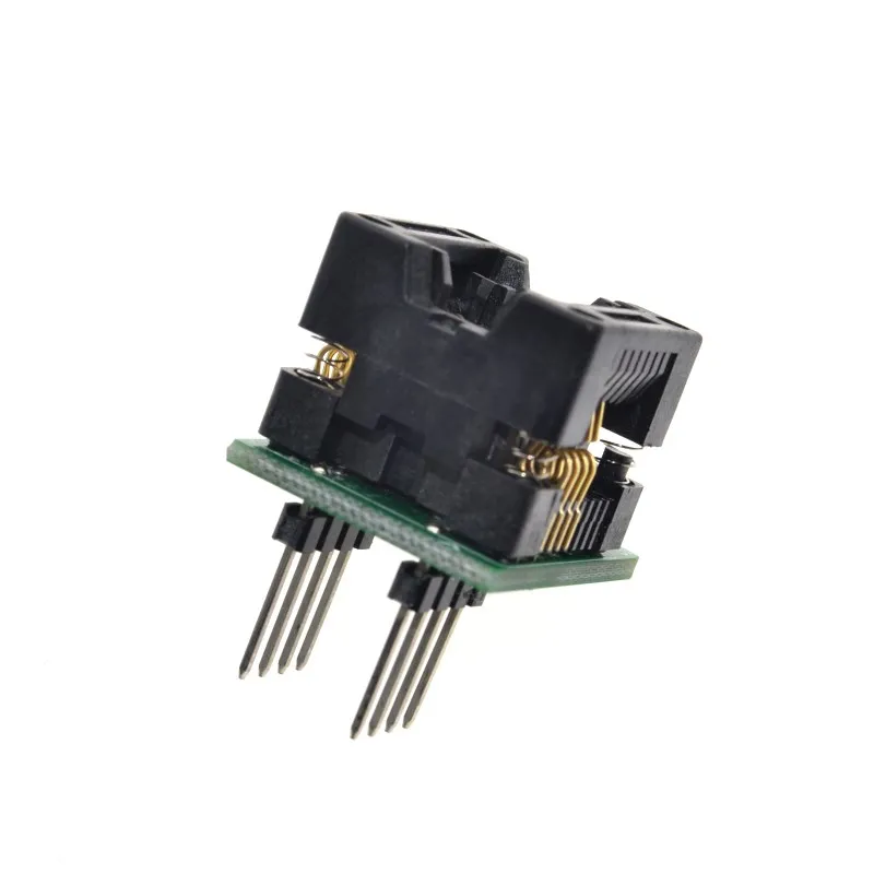
- Standard version: SO8N, −40 to 85 °C. On request, with a minimum order quantity: −40 to 105 °C and −40 to 125 °C grades, plus UFQFPN 3×3 mm and WLCSP 1.7×1.42 mm packages.
Key specifications
| Parameter | Value |
|---|---|
| DMX reception | 1 to 512 channels, full universe buffered |
| RDM PIDs | 11 (listed in the FAQ) |
| Host interface | I2C slave, address 22 (0x16), 16-bit register addressing |
| I2C speed | 100 kHz, 400 kHz or 1 MHz, set by the I2CSPD pin |
| Supply | 3.3 V; SCL, SDA, RX/TX and DIR are 5 V-tolerant |
| Supply current | 3.5 mA typ., 4.1 mA max. at 85 °C ambient |
| DMX/RDM line | UART (RX/TX + DIR) to an external RS485 transceiver |
| Non-volatile memory | 10,000 write cycles; 30-year retention after 1,000 cycles at 85 °C (characterization data) |
| Package | SO8N; UFQFPN 3×3 mm and WLCSP 1.7×1.42 mm on request |
| Ambient temperature | −40 to 85 °C; −40 to 105 °C and −40 to 125 °C on request |
Videos
This company and the products provided herein are developed independently and are not affiliated with, endorsed by, or associated with any official protocol or standardization entity. All trademarks, names, and references to specific protocols remain the property of their respective owners.