

Arduino DMX Receiver: Controlling an RGB LED with the IS3710
No Comments
Receiving DMX512 on an Arduino UNO is harder than it looks. DMX runs at 250 kbaud, every packet starts with a break that your firmware has to detect, and a full universe carries up to 512 channels that keep arriving whether your code is ready or not. On top of that, the UNO has a single hardware UART, and it’s the one wired to USB, so a UART-based DMX receiver usually means giving up the Serial Monitor.
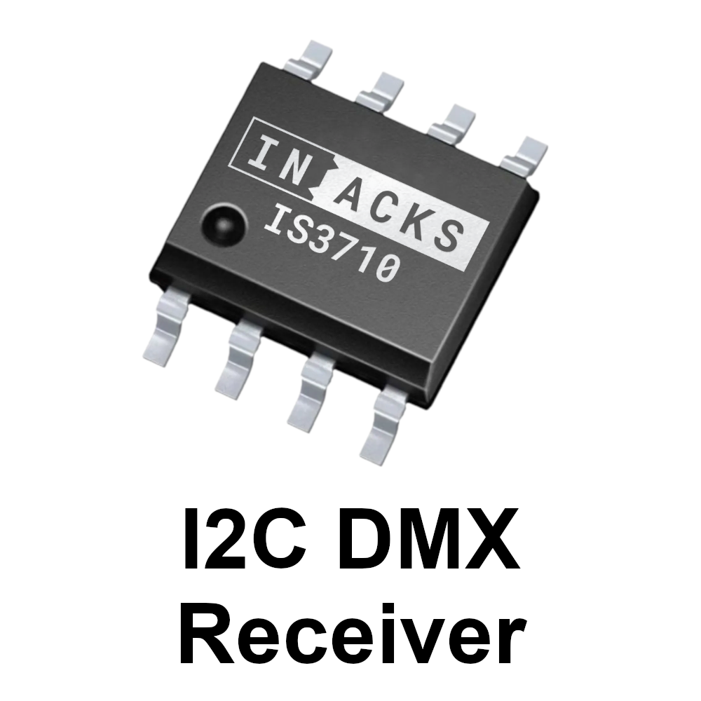
The IS3710 I2C DMX Receiver takes that whole job off your microcontroller. It decodes the DMX512 stream, stores every channel in its own register, and filters out non-DMX data and RDM packets along the way. Your Arduino just reads the channels it needs over I2C, whenever it needs them.
In this post, we walk through the official Arduino example, ISXMPL3710ex1. It uses DMX channels 1, 2 and 3 to set the red, green and blue levels of an RGB LED, which turns your Arduino into a tiny DMX-controlled PAR light.
What You Need
- Kappa3710Ard: the IS3710 evaluation board for Arduino. It’s a shield carrying the IS3710, two daisy-chained XLR-3 connectors and an RGB LED.
- Arduino UNO
- A DMX controller: a lighting console, or a USB-DMX interface with DMX software, plus a DMX cable.
Setup
- Download the example from GitHub, open
ISXMPL3710ex1.inoin the Arduino IDE and upload it to the Arduino UNO. - Plug the Kappa3710Ard onto the Arduino UNO.
- Connect your DMX controller to one of the Kappa3710Ard’s XLR connectors.
- Open the Serial Monitor at 9600 baud. You should see IS3710 Chip detected on I2C! followed by the chip ID.
That’s it. Move the fader for DMX channel 1 and the red part of the Kappa3710Ard’s RGB LED follows it. Channels 2 and 3 do the same for green and blue, and the Serial Monitor prints the three values as they change.
How the Example Works
The IS3710 Register Map
The IS3710 is an I2C slave at address 16 (0x10), and its register map could hardly be simpler: register 1 holds DMX channel 1, register 2 holds channel 2, and so on up to register 512. Register 513 is CHIP_ID, which always reads 16, so it’s a handy way to check that the chip is there. The sketch mirrors this with a few defines:
// IS3710 Register Map
#define DMX_CH1   1
#define DMX_CH2   2
#define DMX_CH3   3
// ...
#define DMX_CH512 512

// IS3710 ID Register:
#define CHIP_ID   513

// I2C address of the IS3710
#define I2C_DEVICE_ADDRESS  16

// Expected value of the CHIP_ID register
#define CHIP_ID_VALUE       16
Since the map goes beyond 255, register addresses are 16 bits wide. That’s the one detail to get right if you write your own driver.
Reading Registers over I2C
All communication with the chip goes through a single helper function, readIS3710Registers(). It sends the 16-bit start address, high byte first, then issues a repeated start and reads as many consecutive registers as you ask for:
bool readIS3710Registers(uint16_t holdingRegisterAddress, uint8_t *buffer, uint16_t length) {

  // Start transmission
  Wire.beginTransmission(I2C_DEVICE_ADDRESS);

  // Send 16-bit register address
  Wire.write((holdingRegisterAddress >> 8) & 0xFF);
  Wire.write(holdingRegisterAddress & 0xFF);

  // End transmission with repeated start
  uint8_t txStatus = Wire.endTransmission(false);

  // Check if address phase failed
  if (txStatus != 0) {
    return true; // error
  }

  // Request bytes
  uint16_t received = Wire.requestFrom(I2C_DEVICE_ADDRESS, length);

  // Check if we got all requested bytes
  if (received != length) {
    return true; // error
  }

  // Read data
  for (uint16_t i = 0; i < length; i++) {
    if (Wire.available()) {
      buffer[i] = Wire.read();
    } else {
      return true; // error (unexpected)
    }
  }

  return 0; // success
}
The function returns false on success and true on error, so a failed address phase or a short read is caught instead of passing bad data to your application. And because consecutive registers can be read in a single transaction, one call can fetch several DMX channels at once.
Detecting the Chip in setup()
setup() starts the I2C bus and the serial port, then reads CHIP_ID. If it returns 16, the sketch prints a confirmation. If it doesn’t, it prints an error and halts. It’s a simple check, but it tells you right away whether the shield is seated properly and responding on the bus.
Driving the RGB LED in loop()
The loop reads three registers starting at register 1 in a single burst, then writes the values straight to PWM pins 9, 10 and 11:
// Read 3 DMX channels starting from channel 1
// Data is stored at dmxData[1], dmxData[2], dmxData[3]
i2cReadError = readIS3710Registers(1, &dmxData[1], 3);

if (i2cReadError == false) {

  // ... print the values to the Serial Monitor ...

  // Map DMX values (0–255) directly to PWM outputs
  analogWrite(9,  dmxData[DMX_CH1]); // Red
  analogWrite(10, dmxData[DMX_CH2]); // Green
  analogWrite(11, dmxData[DMX_CH3]); // Blue

  // Optional delay for easier serial monitoring
  // Remove for maximum refresh rate
  delay(100);
}
Note how the buffer is indexed. dmxData has 513 bytes with index 0 left unused, so dmxData[1] is DMX channel 1. Keeping the array index equal to the channel number makes the code easy to read and hard to get wrong.
DMX values and the UNO’s analogWrite() both use the 0–255 range, so no scaling is needed. The delay(100) is only there to keep the Serial Monitor readable. Remove it and the LED follows the faders as fast as the loop runs.
Adapting the Example to Your Project
- Use your own DMX start address. Real fixtures let the user choose the channel they start at. Just pass that address instead of 1, for example
readIS3710Registers(startAddress, &dmxData[startAddress], 3). - Read more channels. Increase the
lengthargument. On the Arduino UNO, the Wire library transfers at most 32 bytes per request, so read larger blocks in chunks of up to 32 channels. - Drive something else. Replace the
analogWrite()calls with whatever your device needs to do: dimmers, relays, motors, servos or LED strips.
Beyond Arduino
The same register-based approach works on any microcontroller with an I2C port, and there are ready-made examples for other platforms:
- STM32: ISXMPL3710ex2, which reads all 512 DMX channels.
- Raspberry Pi: ISXMPL3710ex4, a Python example, together with the Kappa3710Rasp evaluation board.
- Your own PCB: the schematic example ISXMPL3710ex3. The IS3710 comes in a compact SO8N package and needs an external RS-485 receiver or transceiver.
If your fixture also has to answer RDM requests, take a look at the IS3720. And if you need to send DMX rather than receive it, check out the IS3715 I2C DMX Controller.
Conclusion
With the IS3710 doing the DMX reception, receiving DMX on an Arduino comes down to reading a few I2C registers. No timing-critical code, no break detection, and your serial port stays free for debugging.
The quickest way to try it is the Kappa3710Ard: stack it on an Arduino UNO, upload the example and move a fader. No soldering needed. You’ll find the complete sketch on GitHub, and the datasheet on the IS3710 product page.