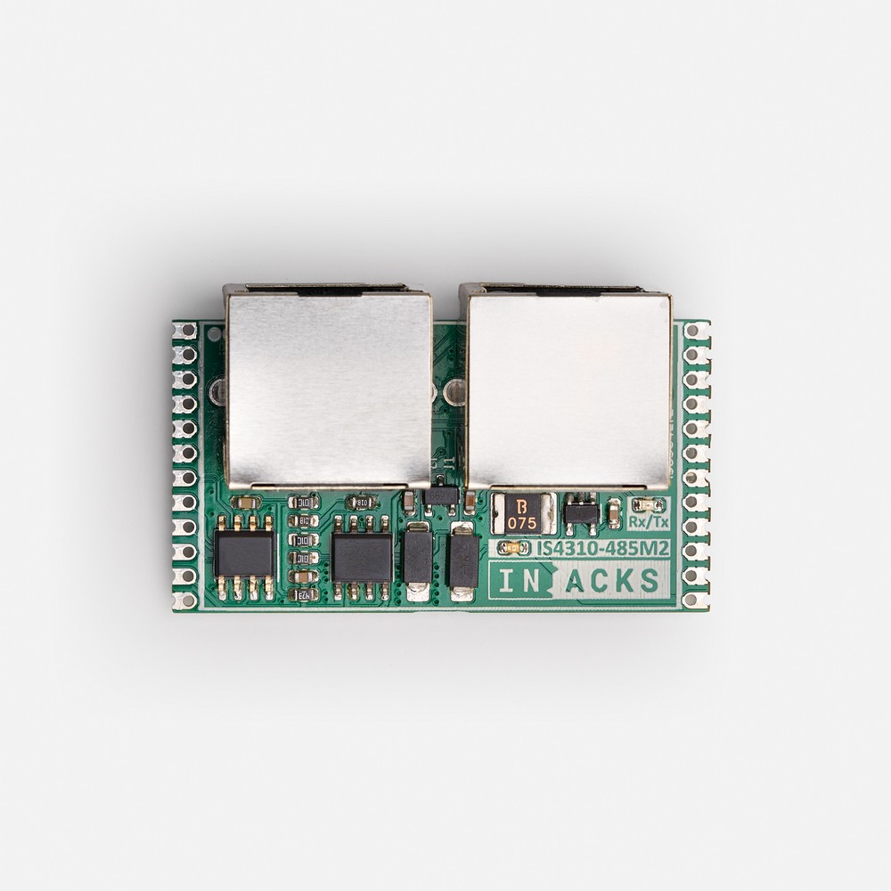
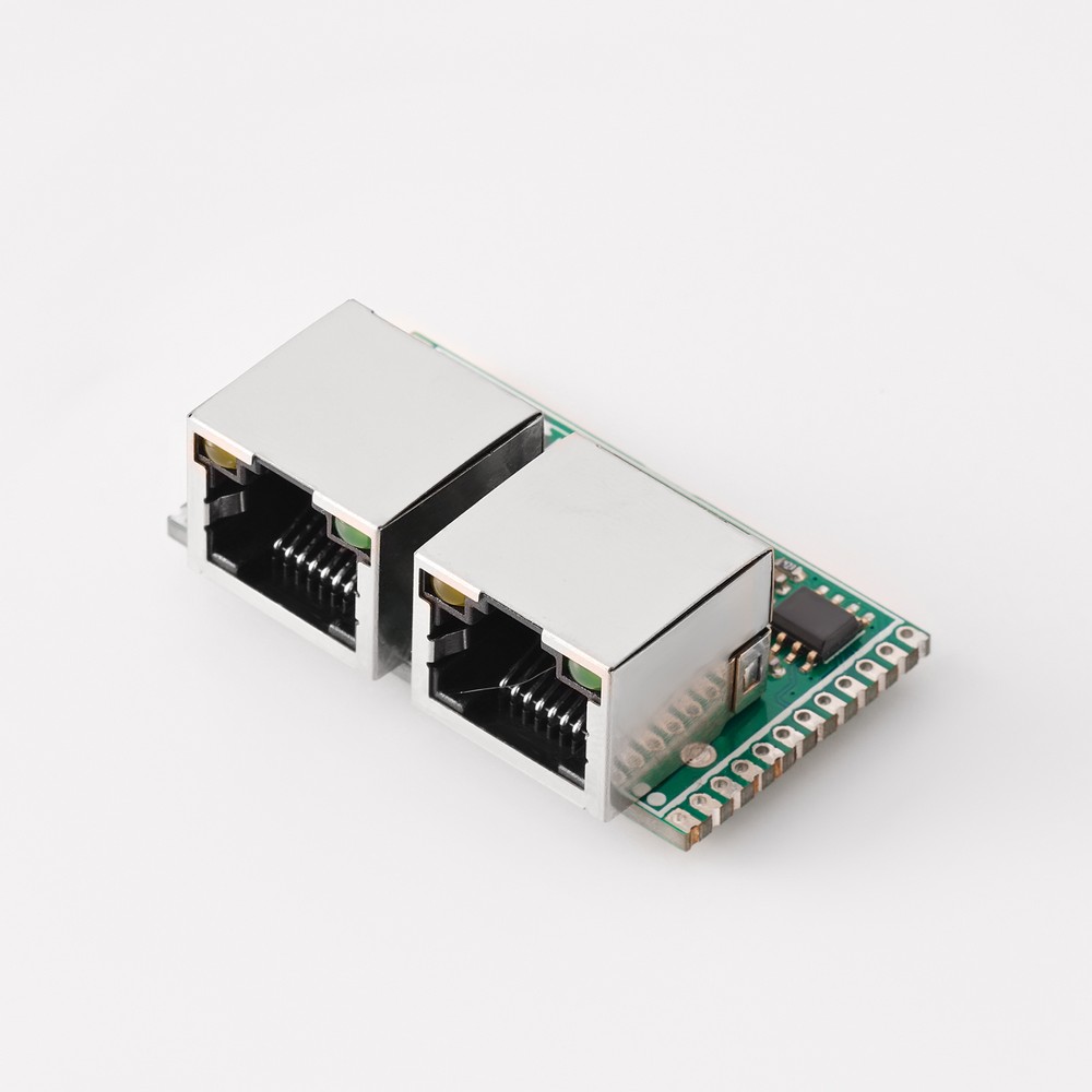
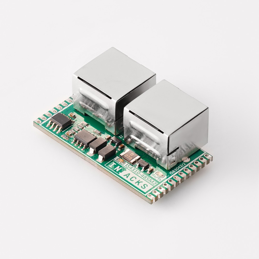
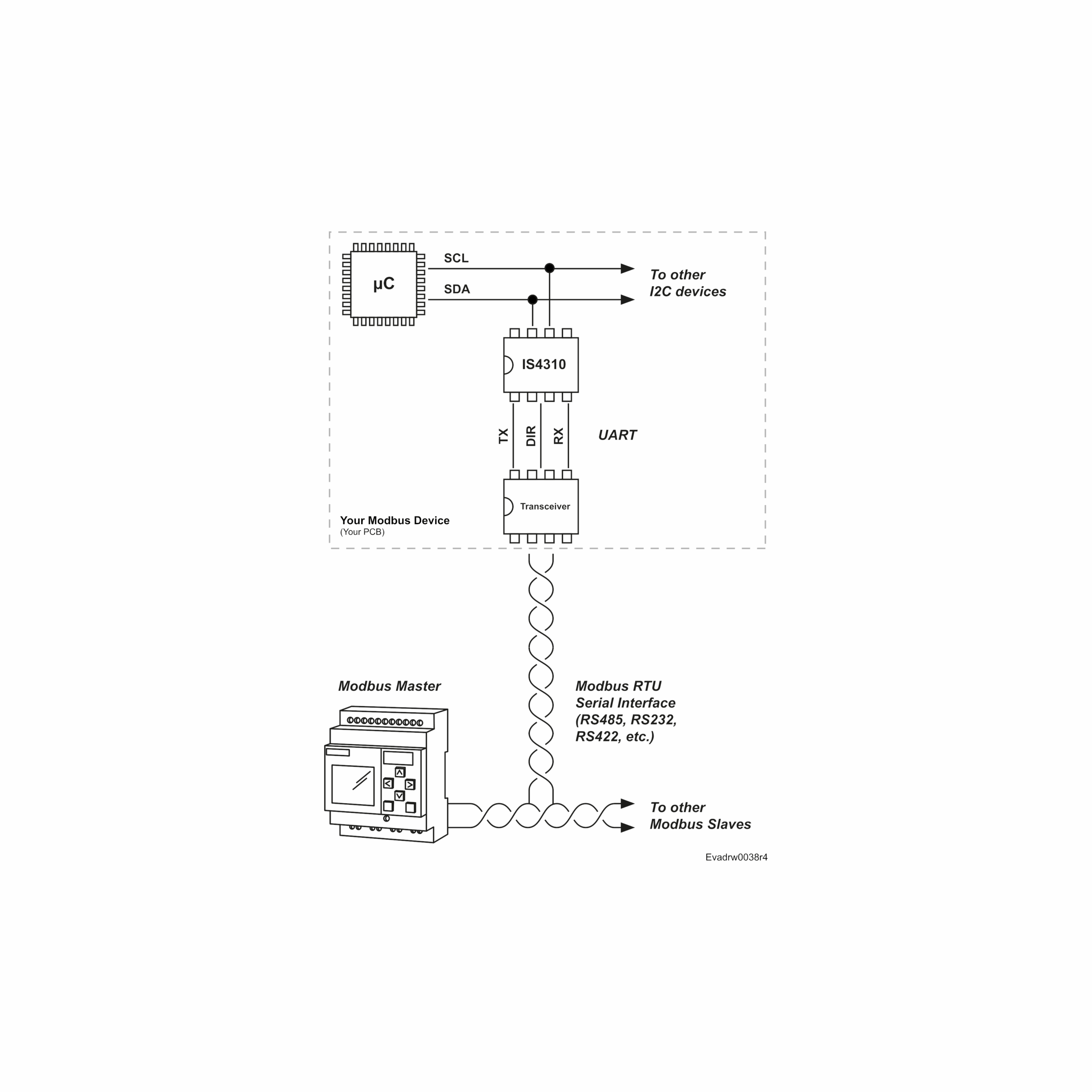
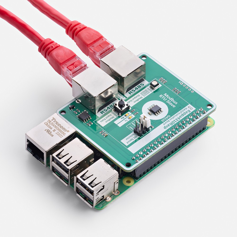
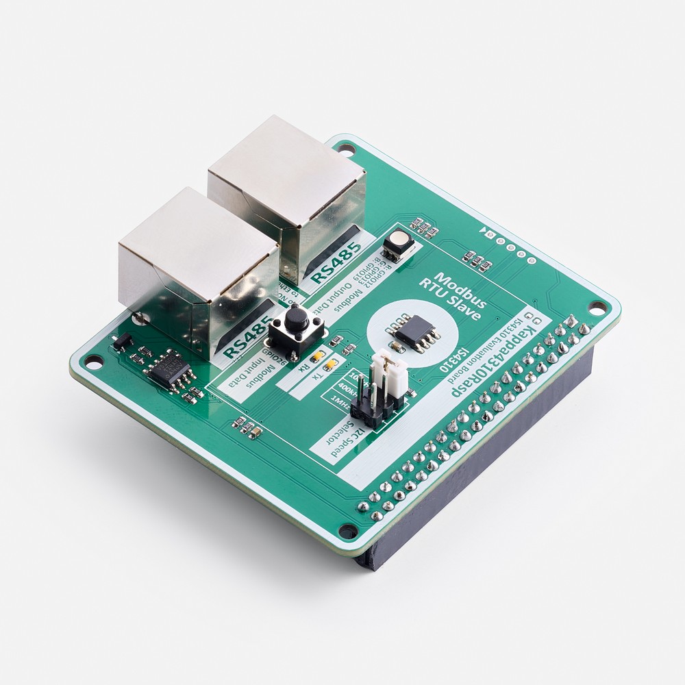
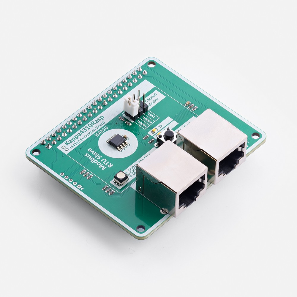
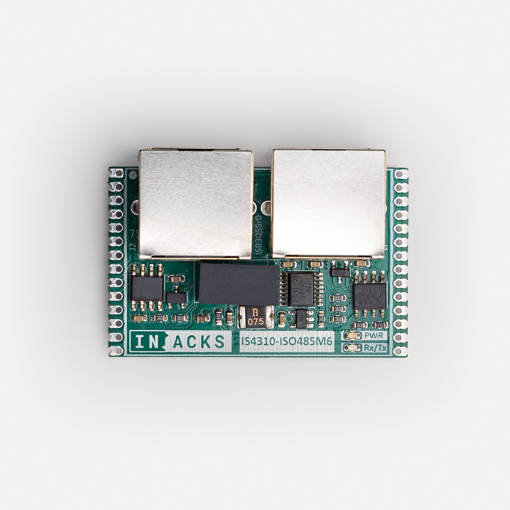
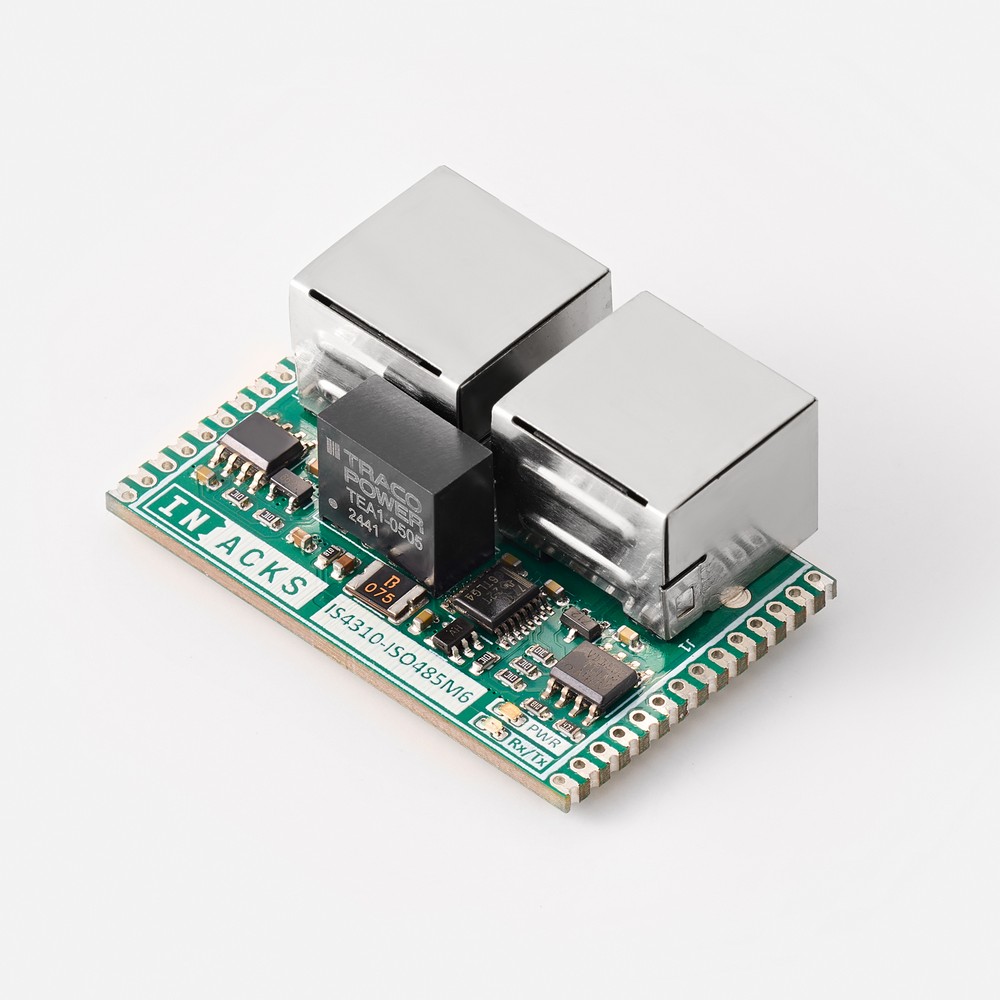
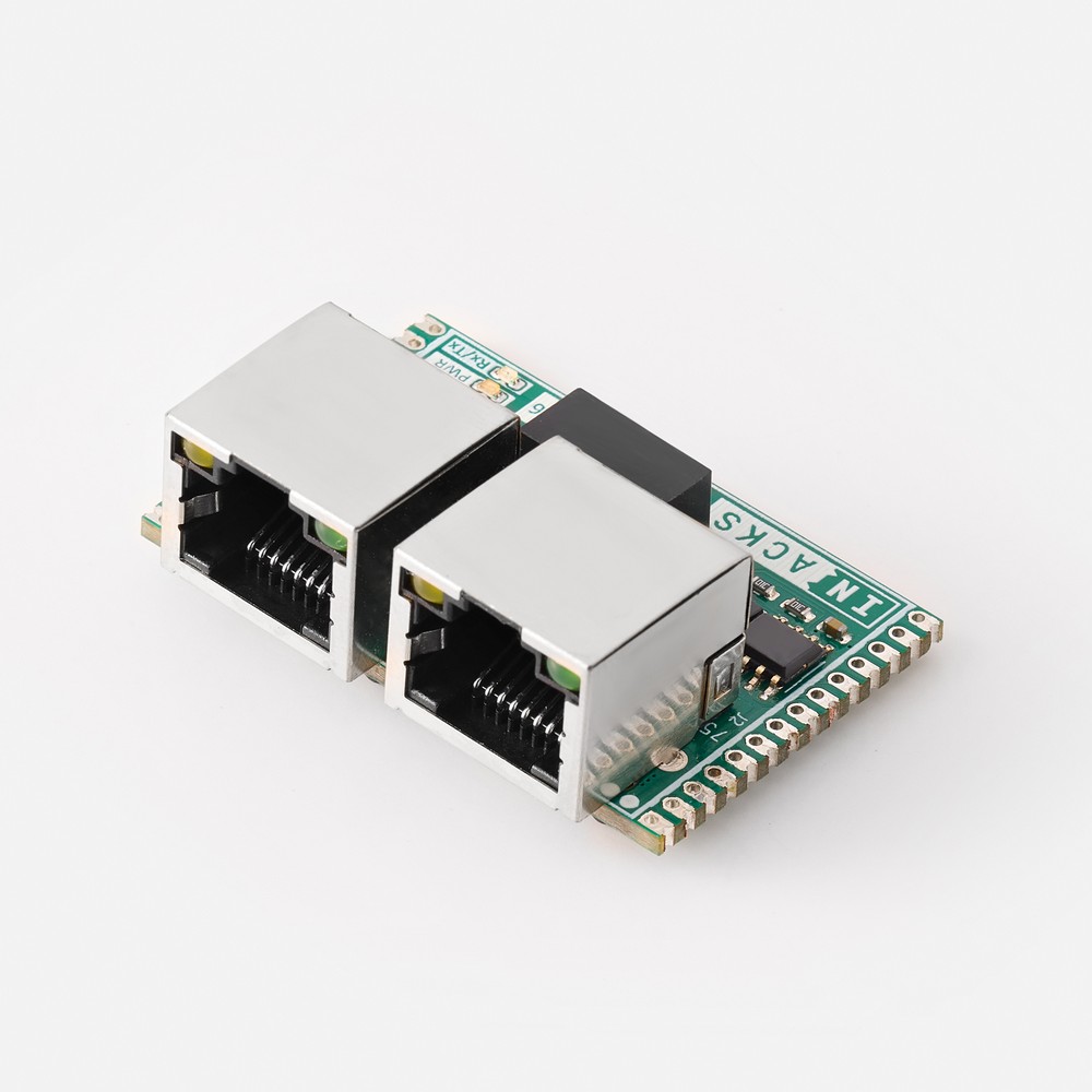
The IS4310-485M2 is a Modbus RS485 module that integrates a Modbus RTU stack chip (IS4310), an RS485 transceiver and two daisy-chained RJ45 connectors.
By integrating this module into your project, you instantly get a working Modbus RS485 interface — just read from or write to the IS4310’s I2C memory registers, which directly map to the Modbus Holding Registers.
This solution minimizes the design effort required to integrate a Modbus RTU Slave with an RS485 physical layer.
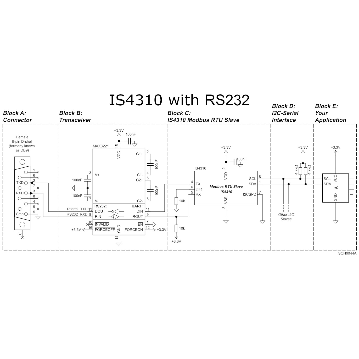
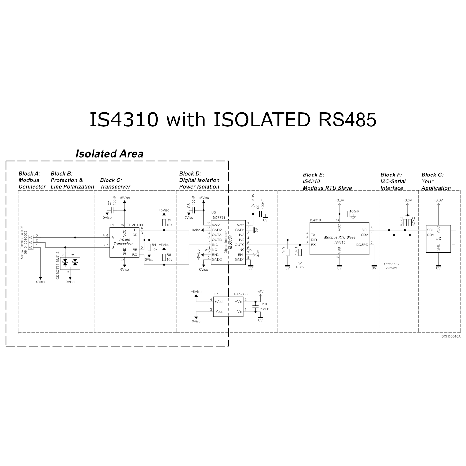
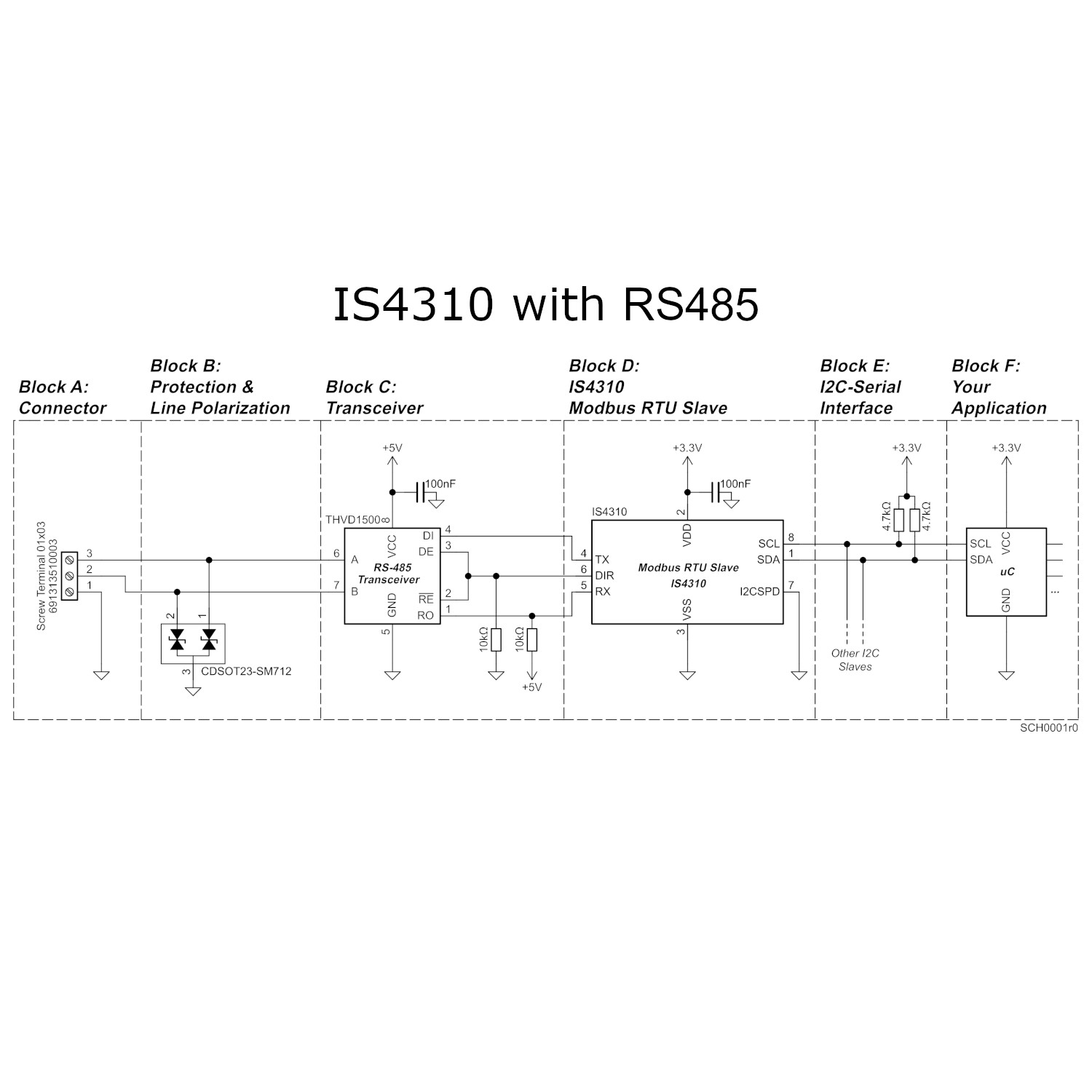
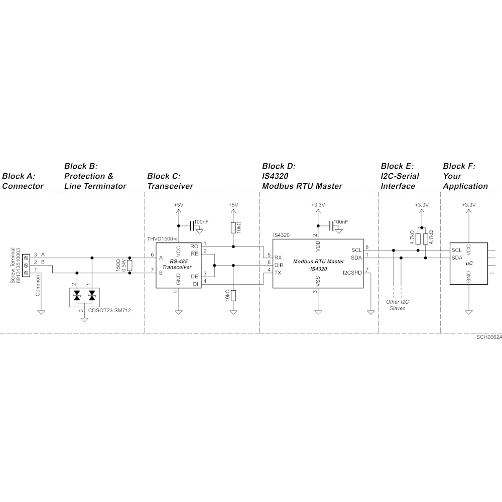
Optionally, you can integrate the IS4310 chip in your own design to minimize costs and customize the connector. Example schematics can be found in the IS4310 datasheet.
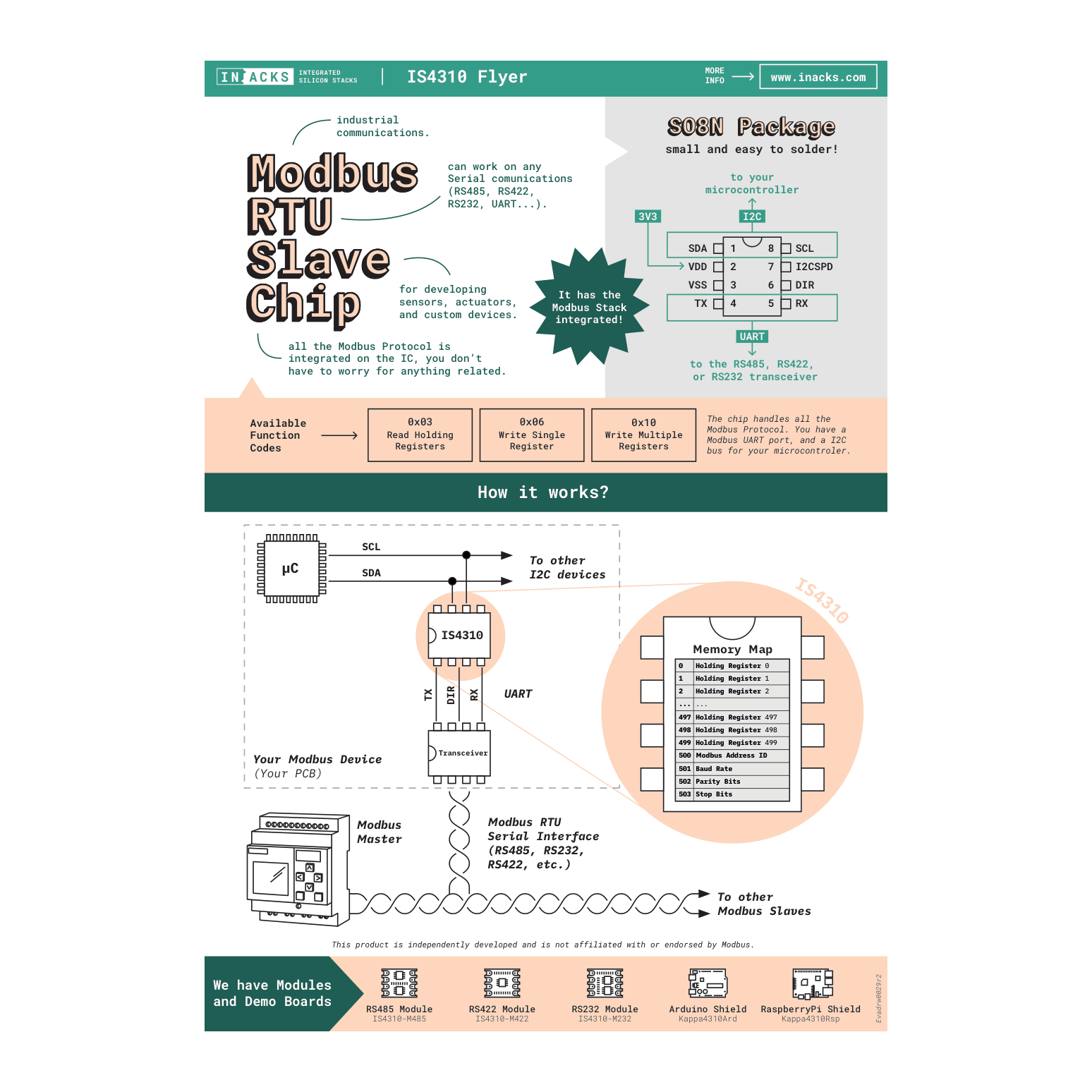
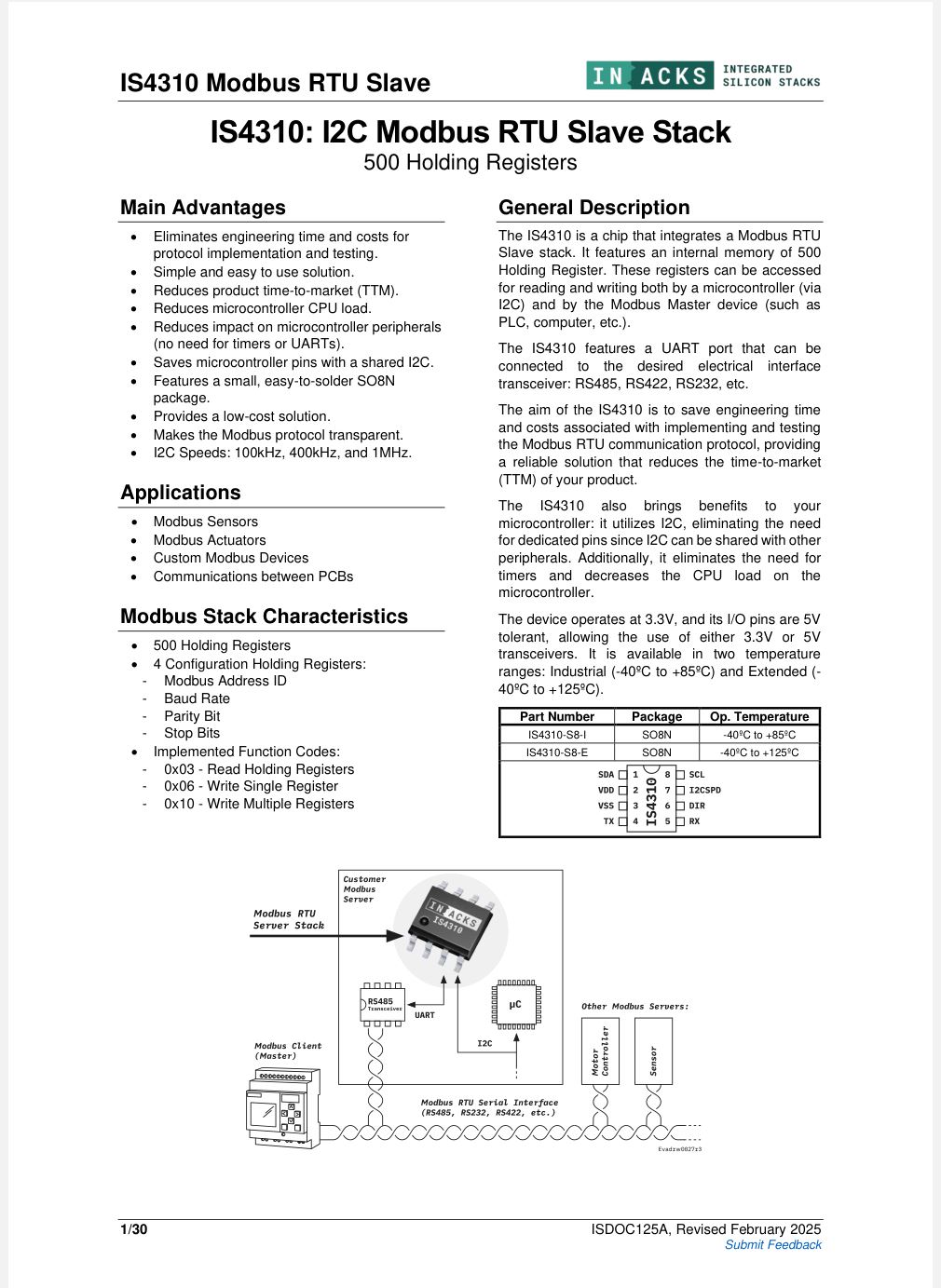
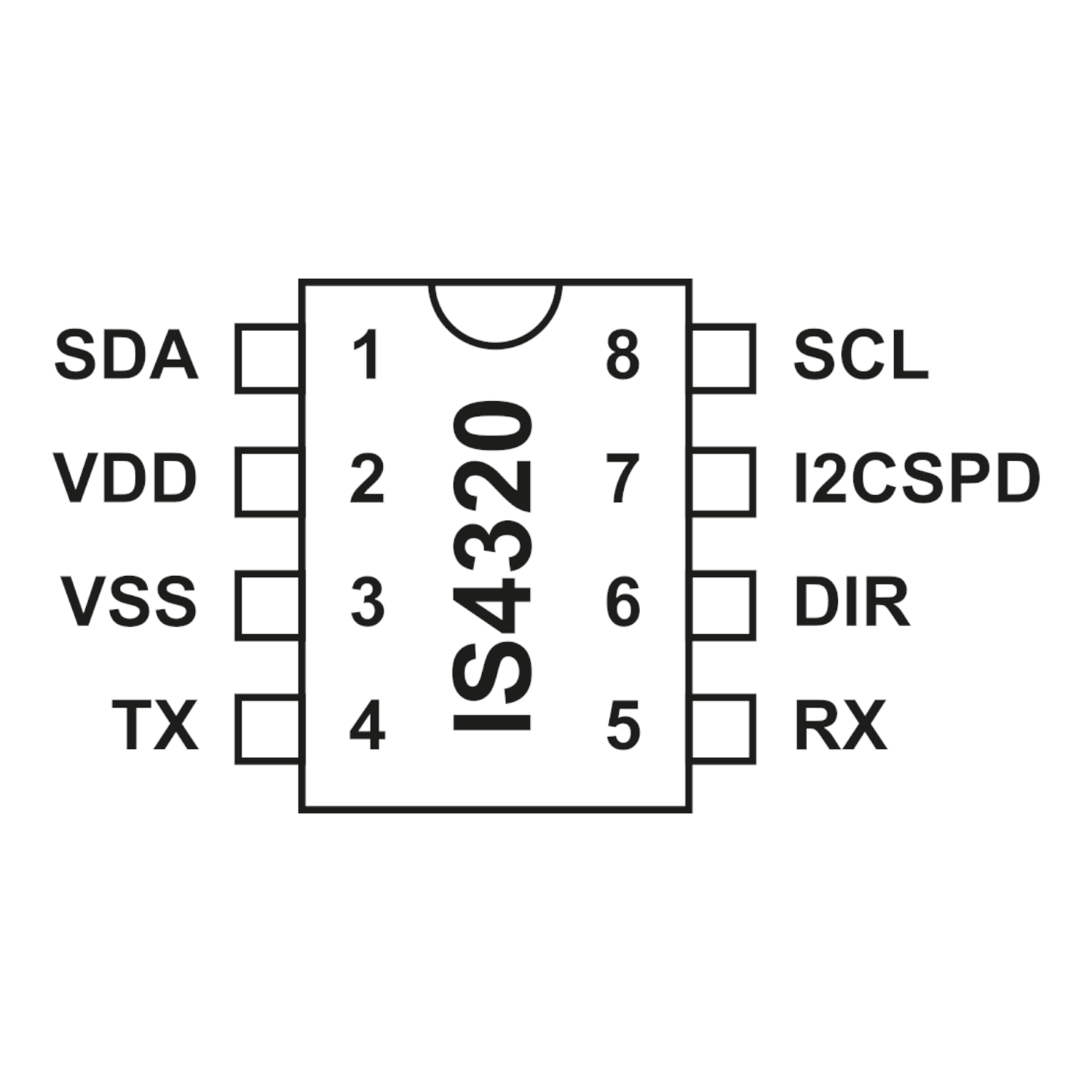
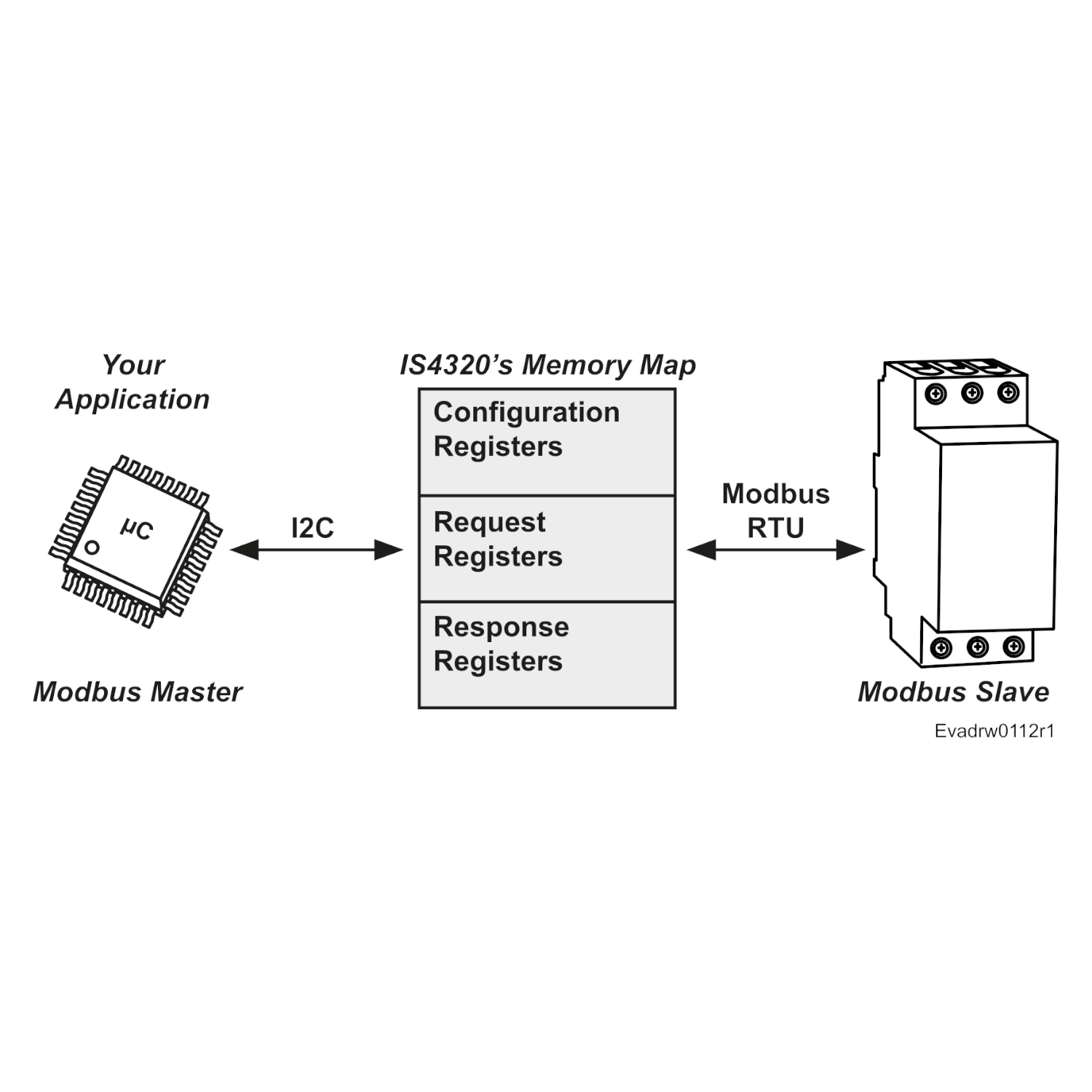
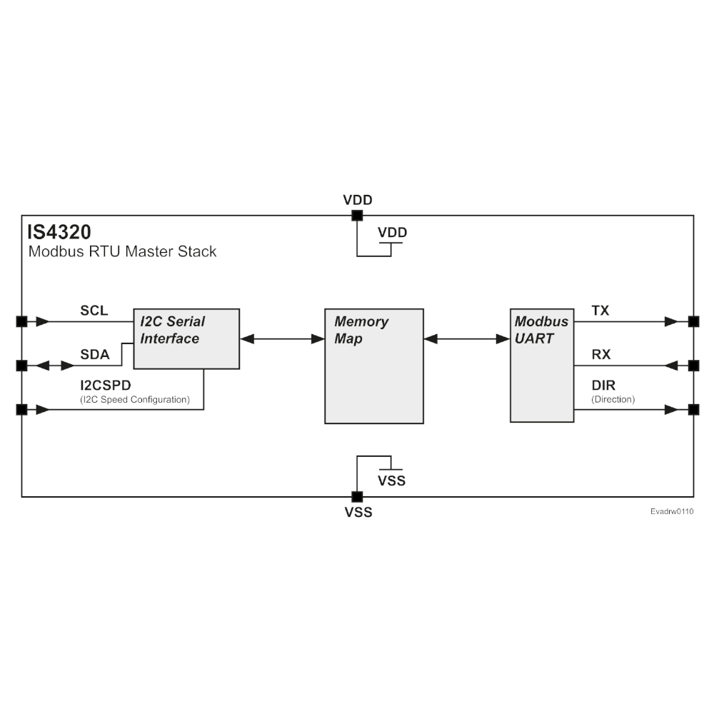
The IS4310 is a chip that integrates a Modbus RTU Slave stack. It features an internal memory of 500 Holding Registers, accessible by both a microcontroller (via I2C) and a Modbus Master device (e.g., PLC, computer, etc.).
You can use the IS4310 in three modes:
- As a Sensor → your microcontroller writes data to the chip via I2C.
- As an Actuator → your microcontroller reads data from the chip via I2C.
- Mixed → your microcontroller reads and writes data to the chip via I2C.
Just read/write the registers you need — no protocol stack required.
The goal of the IS4310 is to eliminate the engineering effort typically required to implement and validate Modbus RTU communication. It offers a reliable, ready-to-use solution that helps reduce development time and speed up your time-to-market (TTM).
How does the module work?
The module provides two interfaces:
- A castellated hole I2C interface for your microcontroller, FPGA, Arduino, Raspberry Pi, etc. This is where your system reads and writes Modbus data.
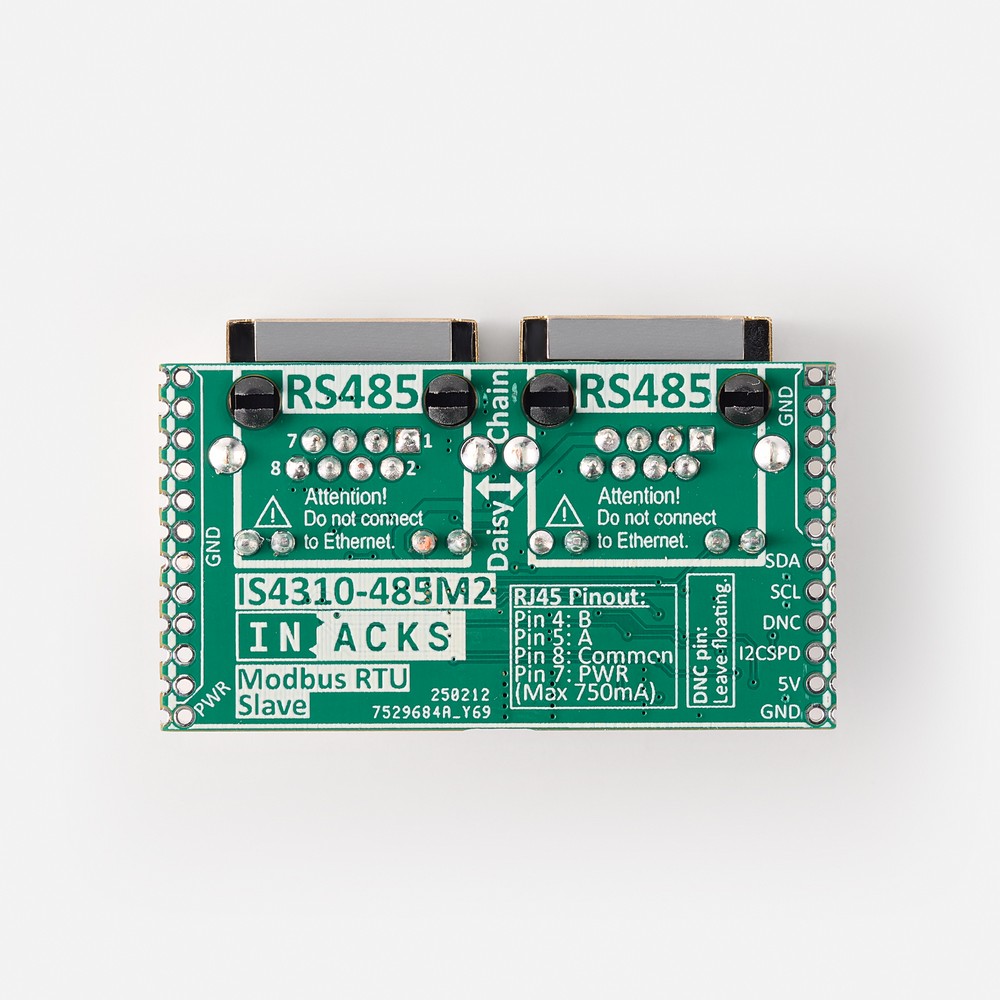
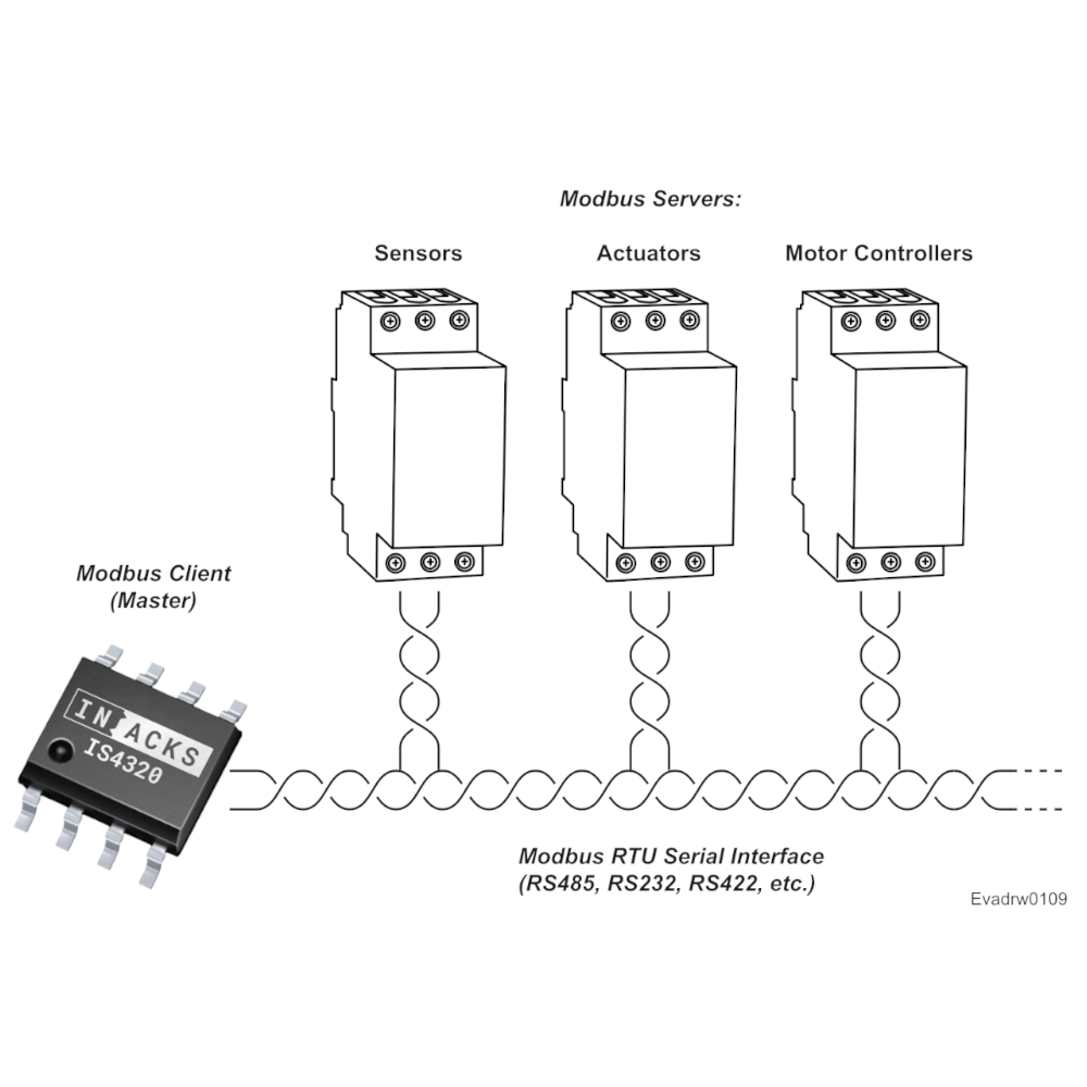
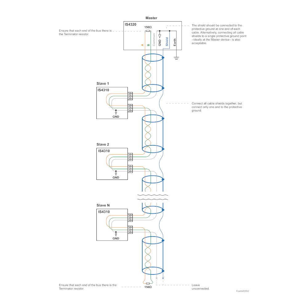
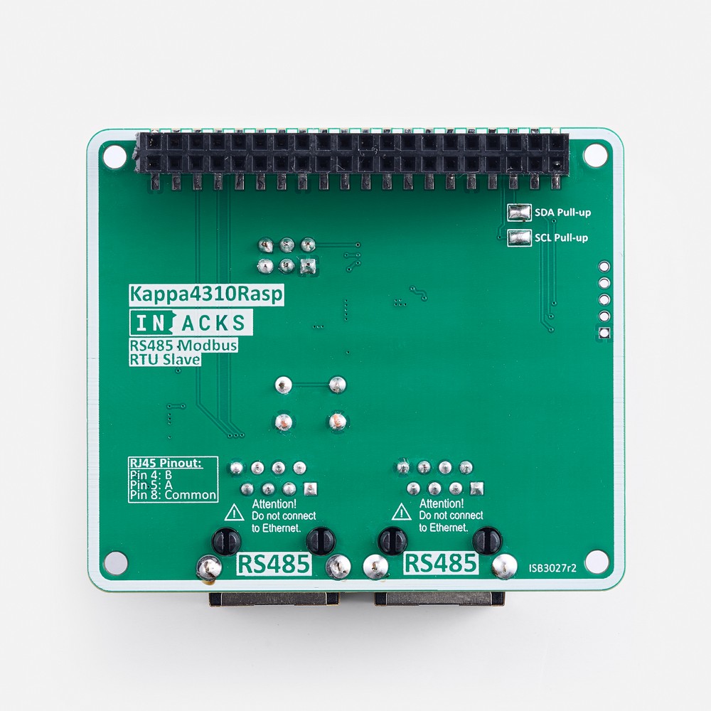
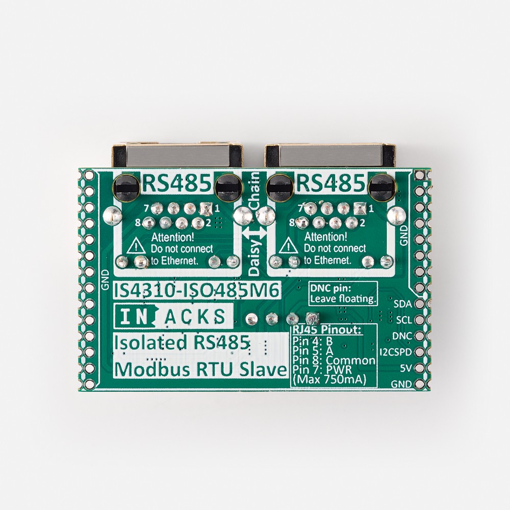
- An RJ45 RS485 output, which serves as the fieldbus interface. It connects the module to the Modbus bus, allowing communication with slave devices and the Modbus master (a PLC, computer, or machine).
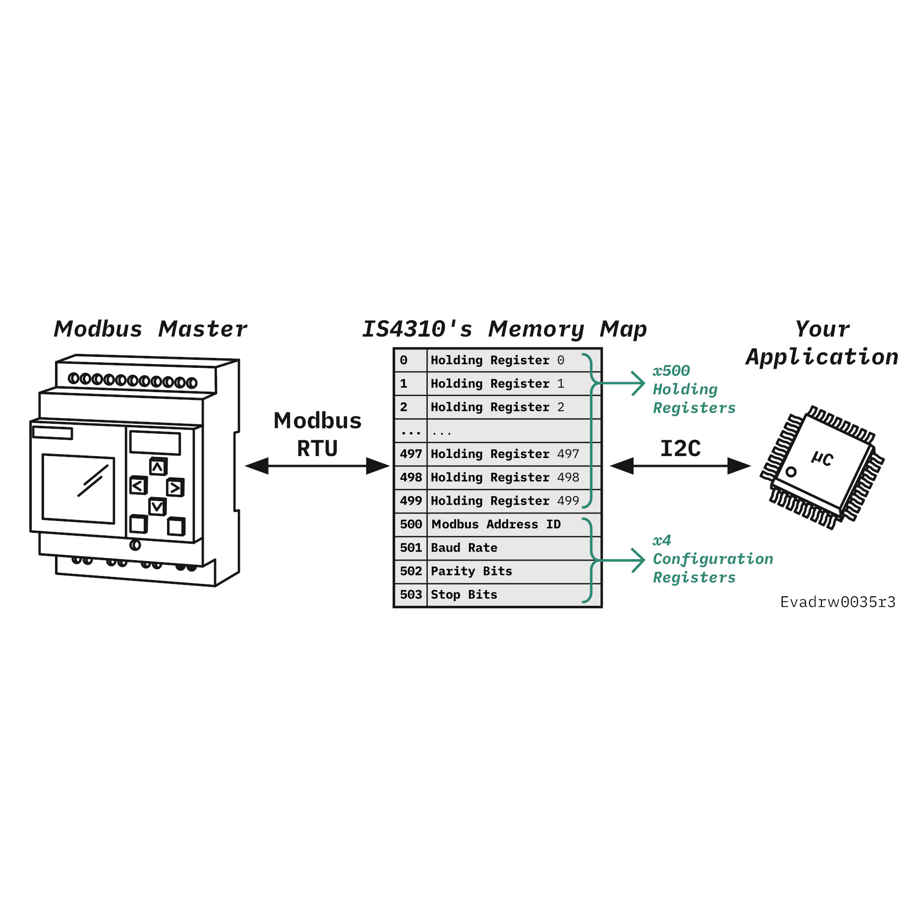
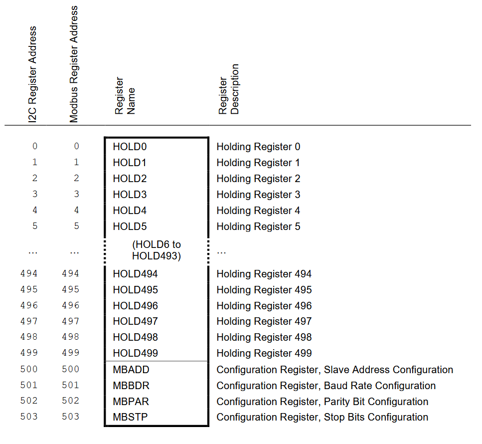
The internal memory is composed of 504 registers:
- 500 Holding Registers for user data.
- 4 Configuration Registers for communication settings: Modbus Slave ID, Baud Rate, Parity, Stop Bits.
The 500 Holding Registers are the key:
Whatever you write to the 500 Holding Registers via I2C will be accessible by the RS485 master device — and vice versa: whatever the RS485 master device writes to the 500 Holding Registers will be accessible by your microcontroller via I2C.
Default Module Settings
Default Modbus Settings:
- Modbus Slave ID:
1 - Modbus Baud Rate:
19200 bps - Modbus Parity:
Even - Modbus Stop Bits:
1
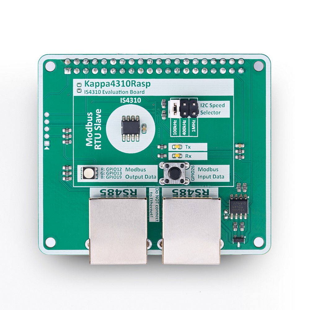
Default I2C Settings:
- I2C Slave Address:
0x11 (fixed) - I2C Speed: Depends on pin 7:
100 kHz (pin 7 to GND), 400 kHz (pin 7 to 3.3V/2), 1 MHz (pin 7 to 3.3V)


Reviews
There are no reviews yet.