
Skip to main contentSkip to footer

I2C/UART 4-20mA Current Loop Receiver Module – IS4420-M1

I2C/UART current loop receiver module. Read a 4-20mA loop from your microcontroller in mA or %, over I2C or as a UART text line, without designing any analog circuitry.

Current Loop Input:
– Range: 0 to 21.50 mA, 2-wire and 3-wire loops
– Resolution: 0.01 mA and 0.1 %
– Factory calibrated at 4 mA and 20 mA

I2C Interface:
– Addresses: 26 to 30 (5 selectable)
– Speeds: 100 kHz, 400 kHz, 1 MHz
– Voltage: 3.3 V

UART Output:
– One text line about every 103 ms
– 115200 baud, no commands needed

Module:
– Power supply: 3.3 V
– Size: 12.70 Ɨ 10.16 mm

In stock

Volume pricing

Qty. Price
1 - 10 $4.00
11 - 50 $3.60
51 + $3.00
SKU: IS4420-M1

I2C/UART Current Loop Receiver for Your Microcontroller

Download IS4420-M1 Datasheet

The IS4420-M1 is an I2C/UART current loop receiver module. It reads a 4-20mA current loop and gives your microcontroller the loop current in mA or as a percentage, over I2C or as a line of text on its UART output. As a result, you can add a 4-20mA input to your product without designing any analog circuitry.

The loop current flows through a precision 150 Ī© resistor on the module. The module measures it, averages each reading over 100 ms to reject 50 Hz and 60 Hz noise, and converts it to milliamps. In addition, INACKS calibrates every module at 4 mA and 20 mA before shipping.

Applications

  • Sensors and transmitters: read 4-20mA pressure, temperature, flow and level transmitters from your microcontroller.
  • Controllers and data loggers: add 4-20mA analog inputs to your own designs.
  • PC monitoring: read the UART text line on a PC through a USB-to-UART adapter.

How to Read the Loop Current

Over I2C: write the 2-byte register address 0x0000, then read 2 bytes with a repeated START: MA_INT (whole mA) and MA_FRAC (hundredths of mA). For example, 12 and 34 mean 12.34 mA. The next registers hold the percentage and the temperature inside the module.

Over UART: the TX pad sends one line of text about every 103 ms, at 115200 baud, 8N1, so you don’t need to send any command:

12.34mA_+052.1%_+025deg_IS4420M1_ver0

Free Windows Software

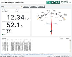
To see the loop current on a PC, connect the TX pad to a USB-to-UART adapter and run IS4420WIN, our free Windows program. It finds the module by itself and shows the current, the percentage and the temperature inside the module, with a needle gauge and CSV logging.

Download IS4420WIN from GitHub

Key Features

  • Input: 4-20mA loop, 2-wire or 3-wire, range 0 to 21.50 mA.
  • Outputs: current with 0.01 mA resolution, percentage of the 4-20mA span with 0.1 % resolution (negative below 4 mA), and the temperature inside the module in °C.
  • I2C interface: 3.3 V, 5 selectable addresses (26 to 30), 100 kHz, 400 kHz and 1 MHz.
  • UART output: transmit only, 115200 baud, one text line about every 103 ms.
  • Factory calibration at 4 mA and 20 mA, which you can also redo over I2C.
  • Power supply: 3.3 V.
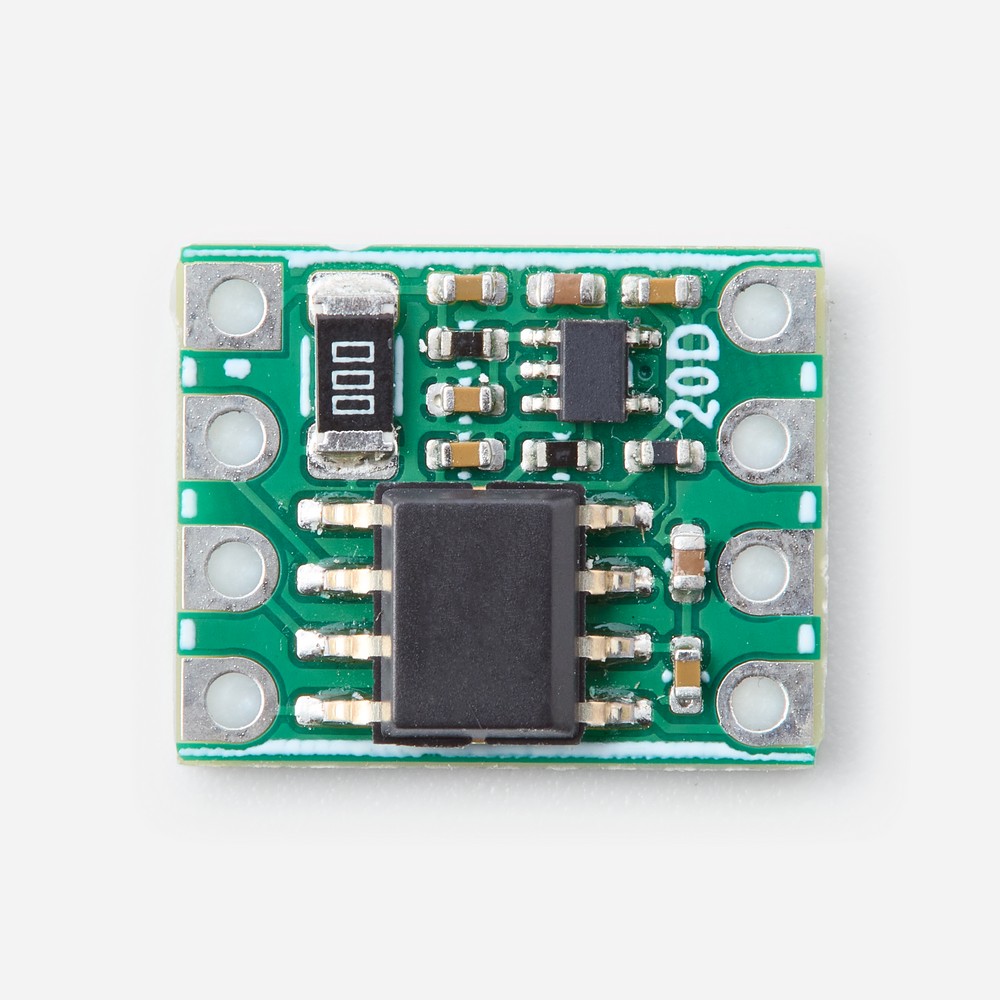
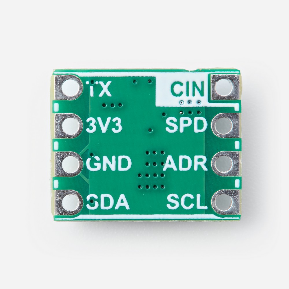
  • Compact module: 12.70 Ɨ 10.16 mm, 8 pads at 2.54 mm pitch.

Documentation

Models

Q: What is the IS4420-M1 used for?

A: To read a 4-20mA current loop from a microcontroller. Use it to read pressure, temperature, flow, level and other 4-20mA transmitters, or to add 4-20mA inputs to your own controllers and data loggers.

Q: Do I need to design any analog circuitry or install any libraries?

A: No. The module measures the loop current and gives you the result in mA and in %. Any I2C driver can read it, for example the Arduino Wire library, and any serial port can read the UART line.

Q: How do I read the loop current over I2C?

A: Write the 2-byte register address 0x0000, then read 2 bytes with a repeated START: MA_INT (whole mA) and MA_FRAC (hundredths of mA). For example, 12 and 34 mean 12.34 mA. Registers 0x0002 and 0x0003 hold the percentage (bit 7 of 0x0002 is the sign), and register 0x0006 the temperature inside the module. Your I2C master must send both bytes of the register address and support clock stretching.

Q: How does the UART output work?

A: The TX pad sends one line of text about every 103 ms, at 115200 baud, 8N1, with no command needed. For example: 12.34mA_+052.1%_+025deg_IS4420M1_ver0, followed by CR LF. Connect TX to the RX input of your microcontroller or USB-to-UART adapter, with a 2.2 kΩ pull-up resistor to 3.3 V or 5 V. Every valid line has 37 characters before the CR LF.

Q: Which I2C addresses and speeds can I use?

A: Five addresses, set with the ADR pad: GND = 26, 1/4 of 3V3 = 27, 1/2 of 3V3 = 28, 3/4 of 3V3 = 29 and 3V3 = 30. Three speeds, set with the SPD pad: GND = 100 kHz, 1/2 of 3V3 = 400 kHz and 3V3 = 1 MHz. For the middle levels, use a resistor divider from 3V3 to GND, for example two 10 kΩ resistors for 1/2 of 3V3. Up to five modules can share the same I2C-serial interface. Set ADR and SPD with the module powered off.

Q: Is the module calibrated?

A: Yes. INACKS calibrates every module at 4 mA and 20 mA before shipping. You can also calibrate it again over I2C with your own reference. The new calibration replaces the factory one.

Q: What happens below 4 mA or above 20 mA?

A: With a 3.3 V supply, the module measures from 0 mA to 21.50 mA. Below 4 mA the percentage is negative (-25.0 % at 0 mA), so you can detect a broken loop. Above 21.50 mA the reading is over-range: the UART line shows EOVER and MA_INT reads 0xFF.

Q: Which loop configurations are supported?

A: 2-wire and 3-wire transmitters. The loop current flows into CIN and returns to GND through a 150 Ī© resistor, so the loop shares GND with the module and your microcontroller: the input is not isolated. At 20 mA the module adds 3.0 V to the loop, so the loop supply must cover this plus the minimum voltage of the transmitter.

Q: What power supply do I need?

A: 3.3 V on the 3V3 pad: the module has no regulator. SDA and SCL are 5 V tolerant, so you can pull them up to 3.3 V or 5 V, and a 5 V microcontroller such as an Arduino Uno needs no level shifter. The TX pull-up can go to 3.3 V or 5 V.

Q: Are the inputs protected?

A: No. Drive CIN only from a 4-20mA loop, with the current flowing into CIN. Never connect a voltage source or the loop supply directly to CIN, never reverse the loop and never reverse the power supply: any of these can destroy the module.

Q: What does the temperature reading show?

A: The temperature inside the module, in whole °C, on I2C and on the UART line. It is meant for monitoring the module: its own heating puts it above the ambient temperature.

Q: What is included?

A: The IS4420-M1 module. The power supply, the microcontroller and the current loop transmitter are not included.

Evaluation boards, Modules & other related products

Evaluation boards, modules, and accessories designed for fast prototyping and easy integration. Featuring standard interfaces and built-in transceivers, they simplify testing and development across platforms like Arduino, Nucleo, or Raspberry Pi. Ideal for adding RS485, RS232, or Ethernet functionality with minimal effort and maximum compatibility.

No results found.

Have a question?

Fill out this field
Please enter a valid email address.
Fill out this field
You need to agree with the terms to proceed